
YouTube
0:00 About full-color LEDs and analog output
1:37 What we will make this time
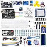
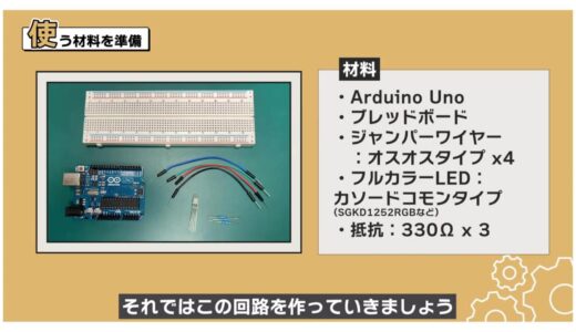
1:43 Preparation of materials to be used
1:53 Schematic
2:18 Assembling the circuit
2:48 Programming
4:23 Write on the Board
4:34 Summary.
Codes used
This is the code used in the video. Please feel free to use it.
//ピン番号の定義
const int RED = 9;
const int GREEN = 10;
const int BLUE = 11;

//PWM Duty比の設定
int redValue = 255;
int greenValue = 0;
int blueValue = 255;

void setup() {
  // put your setup code here, to run once:
  pinMode(RED, OUTPUT);
  pinMode(GREEN, OUTPUT);
  pinMode(BLUE, OUTPUT);
}

void loop() {
  // put your main code here, to run repeatedly:
  analogWrite(RED, redValue);
  analogWrite(GREEN, greenValue);
  analogWrite(BLUE, blueValue);
}
5. Full color LED


- How to use analogWrite function and PWM
- How to use variables and constants
This course is designed for those who are just starting out with electronics, and provides hands-on training on how to build electronic circuits and programming using the Arduino, a typical microcontroller board.
- Arduino Uno $3,150: https://amzn.to/39dcJgb
- ELEGOO Uno $2,399: https://amzn.to/3EGw84F
- KKHMF Uno $1,099: https://amzn.to/3L50Gzs (separate driver installation…)
5. Full color LED
About full-color LEDs and analog outputs
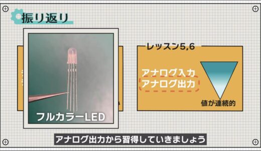
In Lessons 3 and 4, you have learned how to input and output at two levels, HIGH and LOW: digital output and digital input.
In the next two lessons, we will discuss analog outputs and inputs, which allow for input/output at a more granular level.

Let’s start by learning from analog output using full-color LEDs.
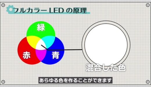
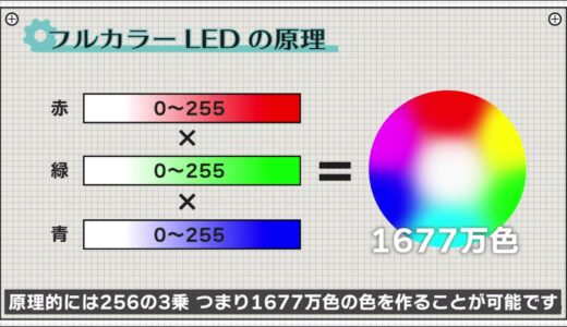
As we learned in science, red, green, and blue are the three primary colors of light, and any color can be created by changing the proportions in which they are blended.
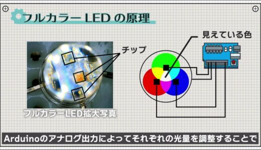
Three LEDs corresponding to these three primary colors are also built into the full-color LED, and by adjusting the light intensity of each LED using the Arduino’s analog output, a variety of colors can be expressed.
In analog output, each color can be adjusted in 256 steps, so in principle it is possible to create 256 to the third power, or 16.77 million colors.
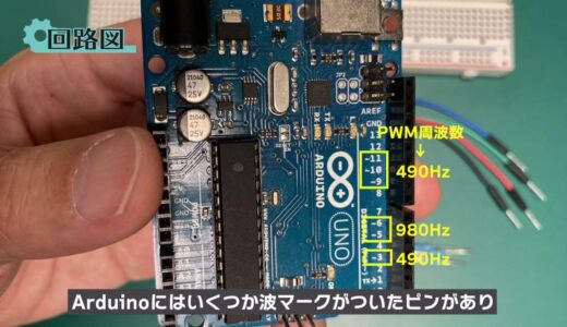
The analog output is a 490 Hz or 980 Hz pulse signal with certain ON and OFF periods, called PWM.

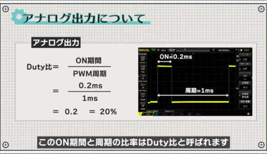
This pulse signal actually makes the LEDs blink at high speed, but at 30 Hz, the human eye cannot perceive the blinking, and the intensity of the light will appear different depending on the duty ratio.The following is a list of the most common problems with the

This property is used to achieve light intensity adjustment .
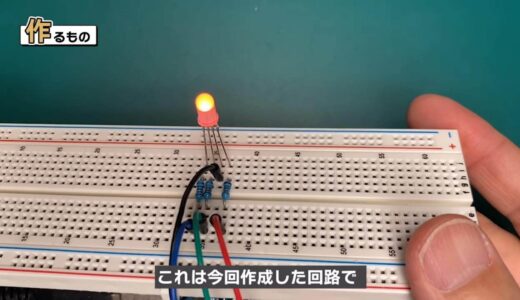
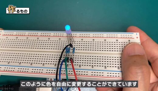
The following figure shows the circuit we have created this time, and as you can see, the color can be changed freely.
 |
 |
What we will make this time
Now let’s make this circuit.
The materials used for this project are an Arduino Uno, a breadboard, four male and four female jumper wires, a full-color LED, and three 330Ω resistors.
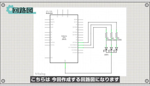
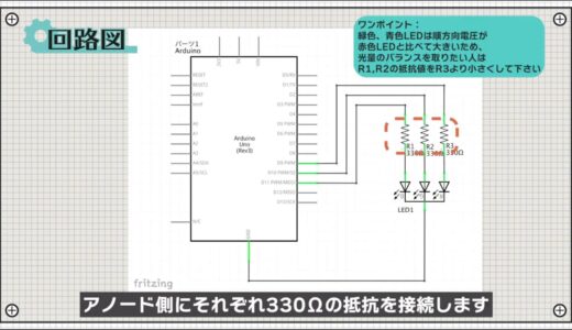
schematic
The following image shows the schematic to be created for this project.
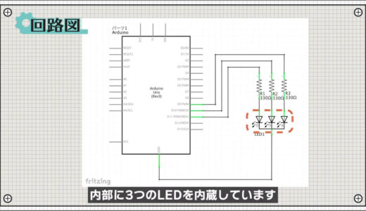
The full-color LED has three LEDs inside, as explained earlier.
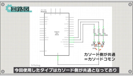
The type used in this project has a common cathode side, and a 330Ω resistor is connected to each anode side.
 |
 |
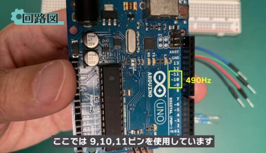
The Arduino has several pins marked with a wave symbol, and these pins serve both digital and analog output functions.
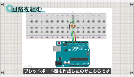
construct a circuit
Next, here is a breadboard diagram following the schematic.
The full-color LED has four legs out, with the longest leg being the cathode, as shown here.
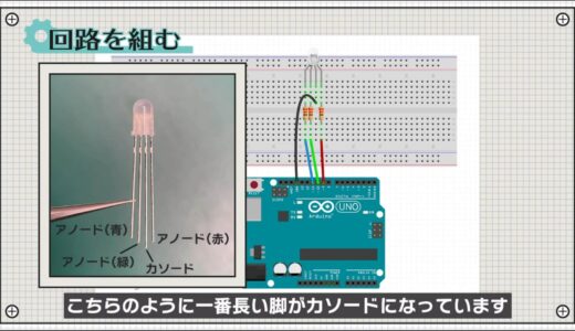
The finished circuit looks like the following.

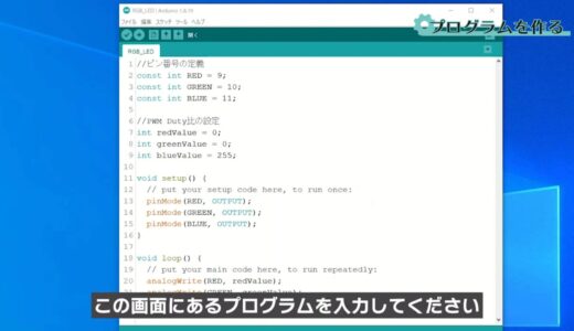
Programming
Start the Arduino IDE, click File→New File, and enter the program on this screen.
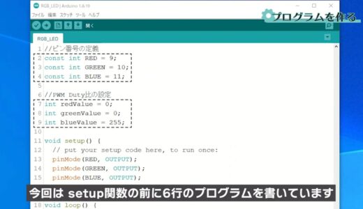
This time, the program is written six lines before the setup function.
The area circled in red here is called a variable, a function that allows data to be named and stored.
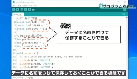
The int preceding it stands for integer, meaning that the variable has an integer value.
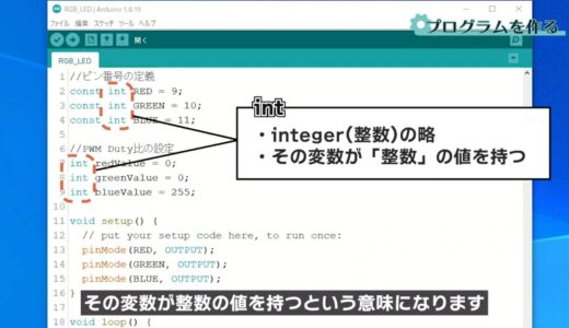
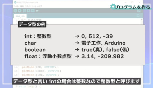
In the programming world, the data type is used to indicate what form of data it is, and in the case of int, it is called the integer type because it is an integer.
- When a value is used in multiple locations
- If you want to give an easy-to-understand name to a value
In this example, it is used where pin numbers are assigned and where the PWM duty is set.

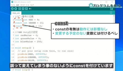
The word const in front of int is a modifier, which makes the variable a constant and allows it to be read-only.
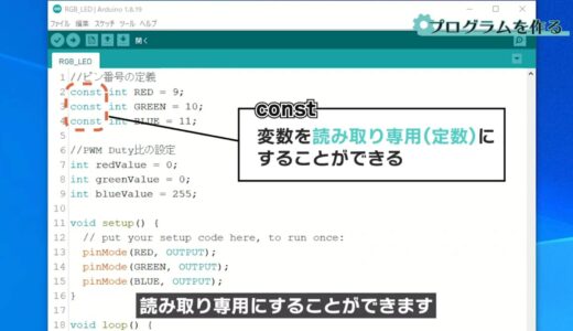
The program itself works fine with or without this, but once a pin number is set, it is basically never changed afterwards, so we constrain ourselves from accidentally changing it.
In the setup function, the RED, GREEN, and BLUE pins are set to output pins respectively.

The loop function is then used to set the PWM Duty ratio for each pin using the analogWrite function.

Duty ranges from 0 to 255, where 0 corresponds to Duty=0 %、255がDuty=100% corresponds to %、255がDuty=100%.
Write on board
Finally, save the file and press the “Write to microcontroller board” button on the toolbar to write the file.
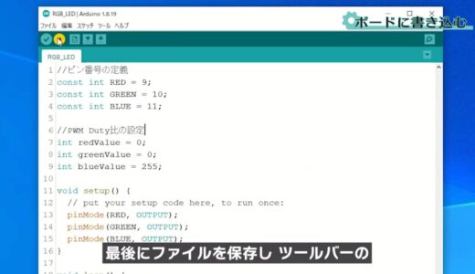
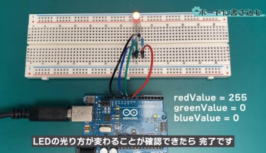
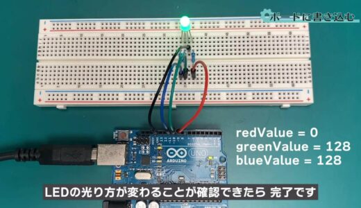
If you can confirm that the LED glows differently each time you change the value of Duty as shown below, you are done.
 |
 |
summary
So this is what we have learned in this issue.
- Usage of analogWrite function and PWM
- How to use variables and constants
On this site, we post videos and articles that allow you to learn electronics construction systematically from zero, including explanations of the minimum knowledge and tools you need to acquire.

\電子工作歴9年の私のイチ押し!ELEGOOの電子工作キット/