
YouTube
0:00 Opening
0:26 Preparation of materials to be used
0:44 Schematic
1:40 Assembling the circuit
2:29 Program Basics
3:27 Programming
4:32 Write on the Board
5:06 Summary.


In this lesson, we will learn thefollowing through hands-on activities under the theme of “3. L-chika”.
- One step flow from circuit creation to programming
- How to use the Arduino IDE
- Arduino programming basics: setup and loop functions, digitalWrite, delay, pinMode
This course is designed for those who are just starting out with electronics, and provides hands-on training on how to build electronic circuits and programming using the Arduino, a typical microcontroller board.
- Arduino Uno $3,150: https://amzn.to/39dcJgb
- ELEGOO Uno $2,399: https://amzn.to/3EGw84F
- KKHMF Uno $1,099: https://amzn.to/3L50Gzs (separate driver installation…)
Codes used
This is the code used in the video. Please feel free to use it.
void setup() {
  // put your setup code here, to run once:
  pinMode(10,OUTPUT);
}

void loop() {
  // put your main code here, to run repeatedly:
  digitalWrite(10,HIGH);
  delay(1000);
  digitalWrite(10,LOW);
  delay(1000);
}
3. L Chica
Now, let’s try to actually run it using an Arduino.
In this lesson 3, you will learn to work with your hands to
- One step flow from circuit creation to programming
- How to use the Arduino IDE
- Arduino programming basics: setup and loop functions, digitalWrite, delay, pinMode
First, let me show you what we will create in this lesson.
As shown below, you can see that the LED connected to the breadboard turns on and off repeatedly every second.
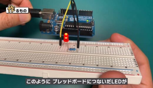
L-chica is the first path that every person who starts electronics work must take, so this is where we will start in this course.
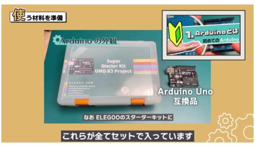
Let’s begin by preparing the materials to be used.
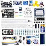
We will use an Arduino Uno, a breadboard, two male and two female jumper wires, a red LED, and a 330Ω resistor.
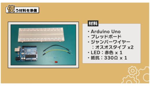
If you use the ELEGOO kit introduced in Lesson 1, all of these are included in the set.
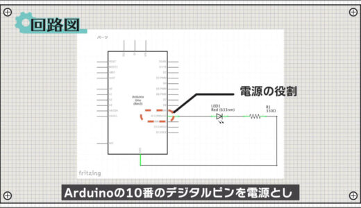
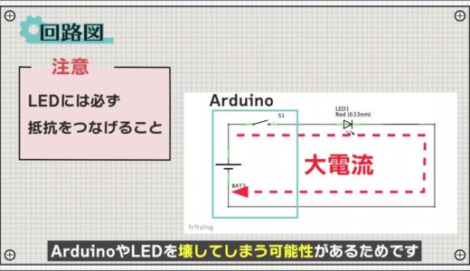
The circuit to be made this time is shown in the schematic diagram below.
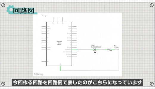
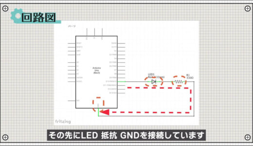
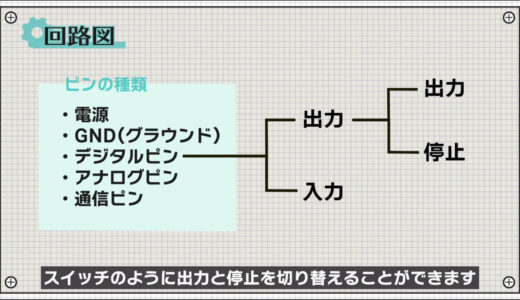
The Arduino’s No. 10 digital pin is used as the power supply, and the LED, resistor, and GND is connected to it.
 |
 |
The digital pins can be programmed to switch between input and output, and in the case of output, a 5 V voltage is output, which can be programmed to switch between output and stop like a switch.
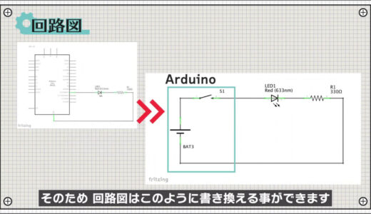
Therefore, the schematic can be rewritten as shown in the following figure.
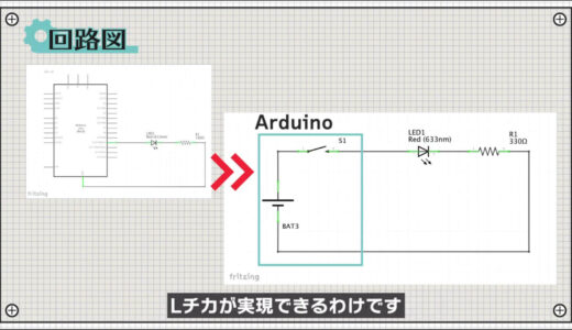
By switching this switch at regular intervals, L-tika can be realized. The L-chica is realized by switching this switch at regular intervals.
Also, be sure to connect a set of resistors to the LEDs.
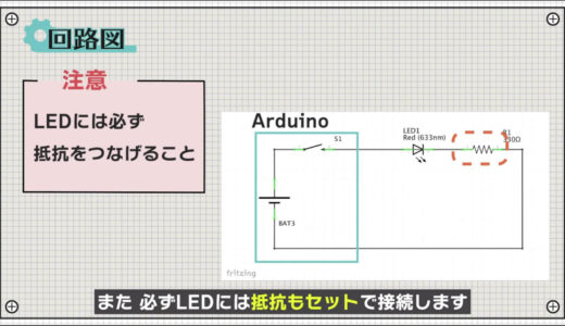
The LEDs will turn on without a resistor, but this is because too much current may damage the Arduino and the LEDs.
Resistance values were obtained using Ohm’s law as shown in the figure below.
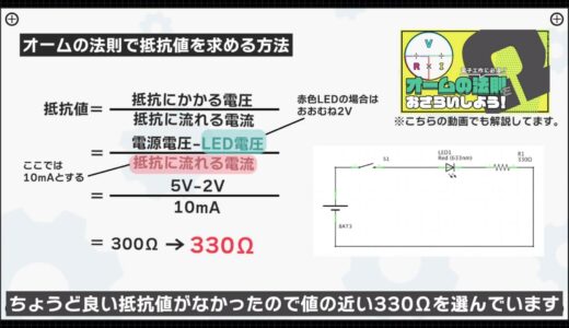
The calculation would be about 300Ω, but there was no resistance value that was just right, so we chose 330Ω, which is close to the value.
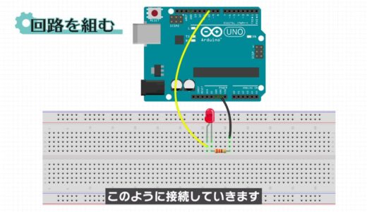
Next, this circuit is connected using a breadboard as follows
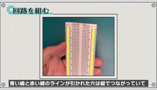
Breadboards are essential tools for electronic construction for the purpose of making circuits quickly and easily.
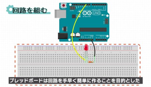
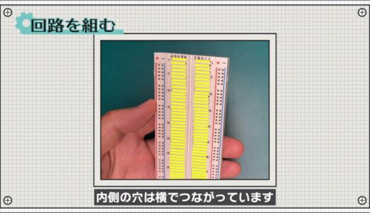
On a breadboard, the holes with blue and red lines drawn on the outside are connected vertically, while the holes on the inside are connected horizontally.
 |
 |
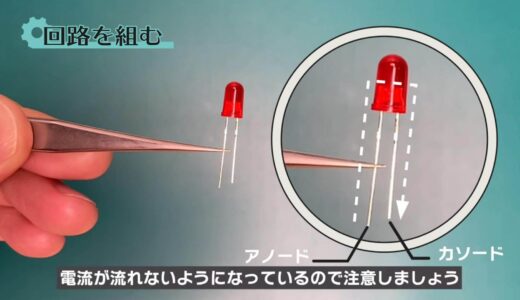
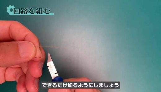
Note that in LEDs, the longer leg of the component is called the anode and the shorter leg is called the cathode, and current can only flow from the anode to the cathode.
On the other hand, there is no difference in resistance due to orientation, so orientation is not a concern.
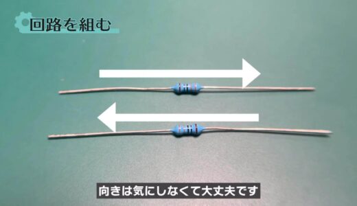
Also, try to cut off as much as possible, since using long legs on parts can easily cause them to wobble and short-circuit with other parts.
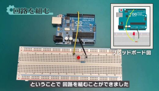
With these precautions in mind, the circuit is assembled using the breadboard diagram as a reference.
So, we were able to build a circuit.
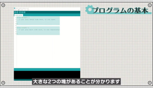
Once the circuit is built, the final step is to program the circuit.
First, if you look at the program screen, you will see that there are two large chunks of code: void setup() and void loop().
In Arduino, two functions that are commonly used in electronic construction are provided from the beginning.
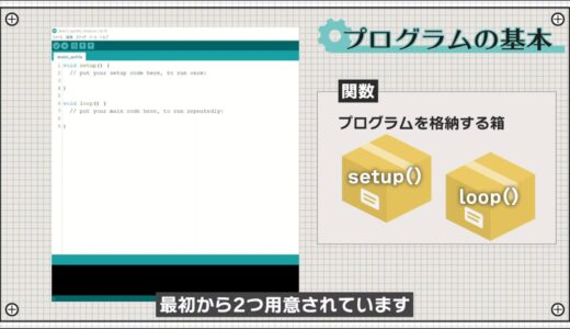
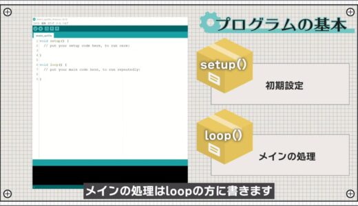
The setup is a function that is executed only the first time the Arduino is started, and the loop is a function that is repeated after the setup is executed.
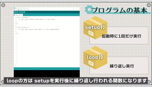
Generally, the initial setup is written in setup, and the main processing is written in loop.
The program is then basically executed in the order of the lines above.
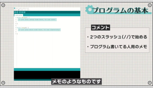
Also, a line that begins with two slashes is a comment, which is like a note to the person writing the program.
Now let’s write the program.
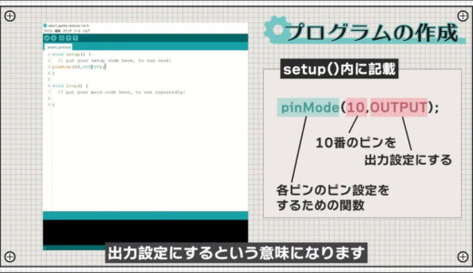
First, write pinMode(10, OUTPUT); in the setup.
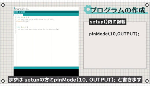
pinMode is a function that is pre-made to set the pin settings for each pin, and when written as follows, it means to set the No. 10 digital pin to the output setting.
Next, add four lines to the loop as shown in the following figure.
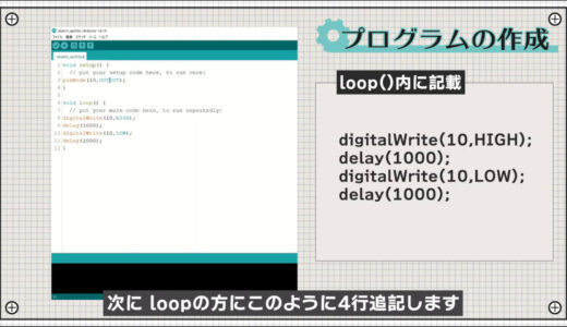
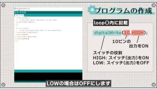
digitalWrite is a function that acts as a switch, turning the pin with the specified number ON when HIGH and OFF when LOW.
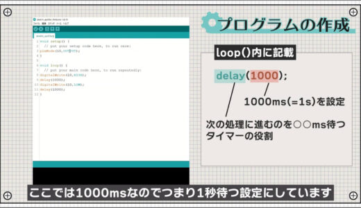
The function “delay” determines how many milliseconds to wait before proceeding to the next process.
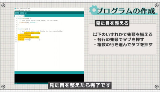
Finally, select the line of the program you have written, press the tab on your keyboard to make it look and feel better, and you are done.
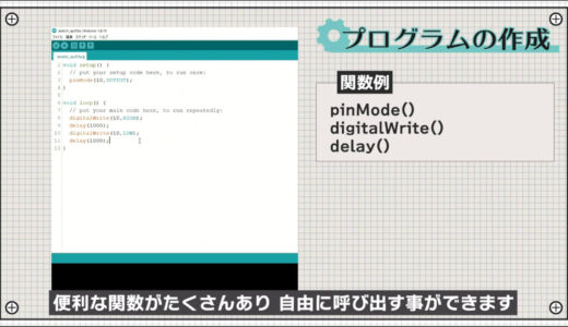
As you can see, Arduino has many useful functions that are pre-built and can be called at will.
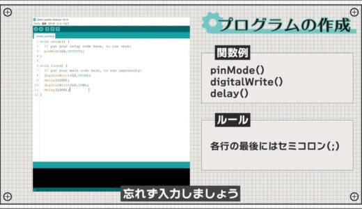
Also, do not forget to enter a semicolon at the end of each line, as this is the rule.
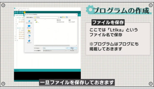
After completing this step, press “File” on the menu bar, then “Save As” to save the file once.
As a preliminary step, select “Arduino Uno” under “Tools” > “Board” in the menu bar and the port labeled “Arduino Uno” under “Serial Port”.
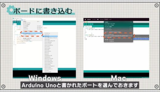
If the name of the Arduino does not appear here, the cable may not be plugged in properly.
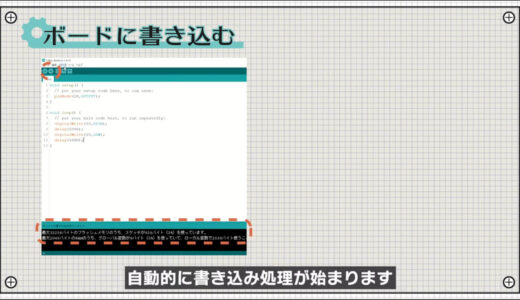
Then, press the “Write to microcontroller board” button on the toolbar, and if there are no errors in the program, the writing process will begin automatically.
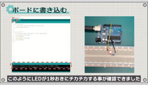
After a few seconds, the process was completed, and we confirmed that the LED flickers every second, as shown here.
summary
This is the third in a series of hands-on introductory courses for beginners who are just starting out in electronics, and this time we have covered the theme of “3. L-Thica.
- One step flow from circuit creation to programming
- How to use the Arduino IDE
- Arduino programming basics: setup and loop functions, digitalWrite, delay, pinMode
Please consider for yourself, based on what you have learned in this article, where you can make changes to your L-chica cycle!
The rest of this article will be explained in the fourth part of the hands-on introductory course for beginners.
On this site, we post videos and articles that allow you to learn electronics construction systematically from zero, including explanations of the minimum knowledge and tools you need to acquire.

\電子工作歴9年の私のイチ押し!ELEGOOの電子工作キット/