
YouTube
0:00 Opening
0:18 Preparation of materials to be used
0:27 Schematic
1:10 Assembling the circuit
1:36 Programming
2:44 Write to the Board
2:56 one-point (e.g. question mark)
3:23 Summary


- Usage of the digitalRead function: INPUT,INPUT_PULLUP
- How to use branch processing (IF statement): if ,else
This course is designed for those who are just starting out with electronics, and provides hands-on training on how to build electronic circuits and programming using the Arduino, a typical microcontroller board.
- Arduino Uno $3,150: https://amzn.to/39dcJgb
- ELEGOO Uno $2,399: https://amzn.to/3EGw84F
- KKHMF Uno $1,099: https://amzn.to/3L50Gzs (separate driver installation…)
Codes used
This is the code used in the video. Please feel free to use it.
If INPUT_PULLUP is not used
void setup() {
  // put your setup code here, to run once:
  pinMode(10,OUTPUT);
  pinMode(8,INPUT);
}

void loop() {
  // put your main code here, to run repeatedly:
  if (digitalRead(8) == HIGH){
    digitalWrite(10,LOW);
  } else {
    digitalWrite(10,HIGH);
  }
}
When INPUT_PULLUP is used
void setup() {
  // put your setup code here, to run once:
  pinMode(10,OUTPUT);
  pinMode(8,INPUT_PULLUP); //INPUTをINPUT_PULLUPへ変更
}

void loop() {
  // put your main code here, to run repeatedly:
  if (digitalRead(8) == HIGH){
    digitalWrite(10,LOW);
  } else {
    digitalWrite(10,HIGH);
  }
}
4. Switch
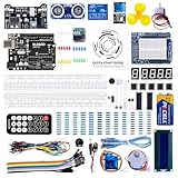
Preparation of materials to be used
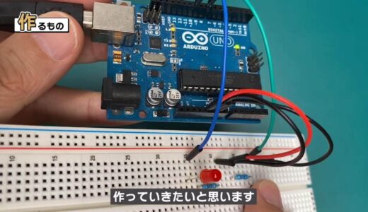
Here we will add a pushbutton switch to the circuit used in Lesson 3 to create a program that turns the LED on while the switch is pressed and off while the switch is released.
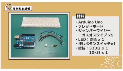
The materials used for this project are shown in the figure below: Arduino Uno, breadboard, 5 male and 5 female jumper wires, red LED, pushbutton switch, and 330Ω and 10kΩ resistors.
schematic
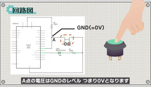
The following figure shows the circuit diagram to be created for this project.
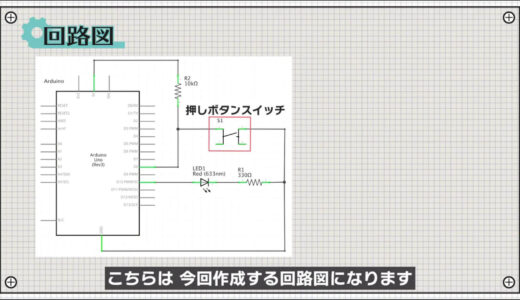
When the switch is pressed, the resistance in the switch is 0Ω, so the voltage at point A is at the level of GND, i.e., 0V.
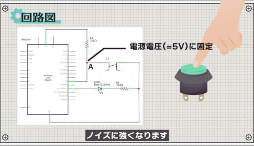
On the other hand, when the switch is not pressed, the switch has a very high resistance value.
For this reason, it is common to connect a resistor of about 10 kΩ, called a pull-up resistor, to the power supply voltage, as shown in the circuit in the figure below.

By connecting this, the voltage at point A can be fixed to the supply voltage when the switch is not pressed, making it more resistant to noise.
construct a circuit
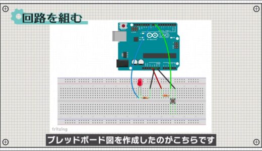
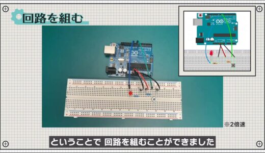
Next, a breadboard diagram is shown below, following the schematic.
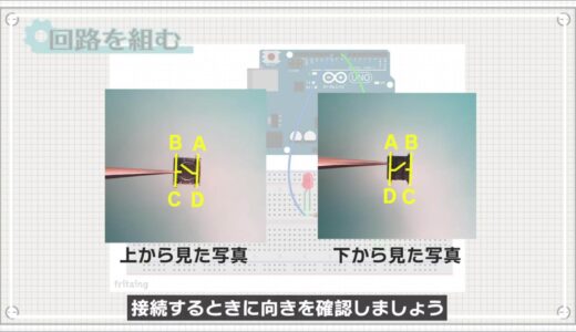
Push-button switches have four legs, which are connected as shown in the figure below, so check the orientation when connecting them.
So, we were able to build a circuit.
Programming
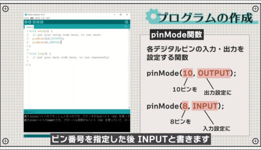
Click “File” -> “New File” and first write two pinMode functions in the Setup function as shown in the following figure.
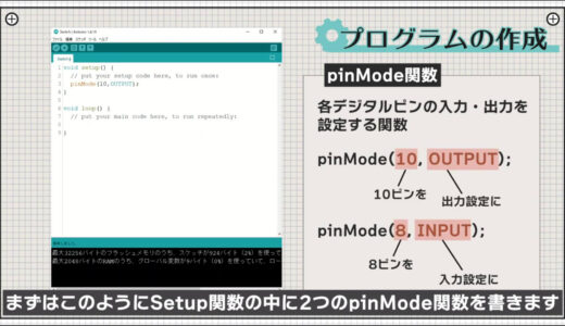
If you want to use a digital pin as an input, write INPUT after specifying the pin number.
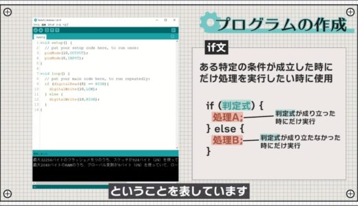
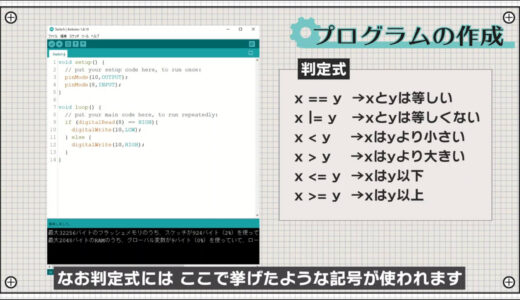
Next, write if statements in the loop function.

The if statement is used when you want to perform processing only when some condition is satisfied, and is often used when you want to change processing depending on whether or not a button is pressed, as in this case.
If the decision expression in the parentheses holds, the processing in the wave brackets that follow is performed; if the decision expression does not hold, the processing in the wave brackets that follow after “else” is performed.
The symbols listed in the figure below are used in the judgment formula.
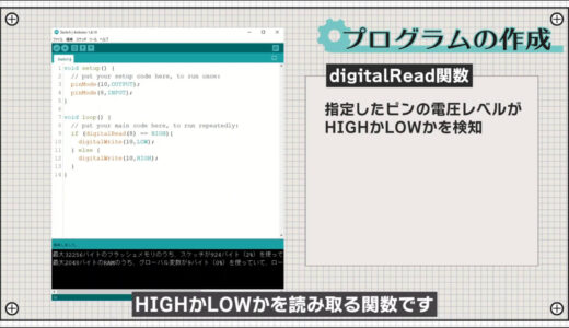
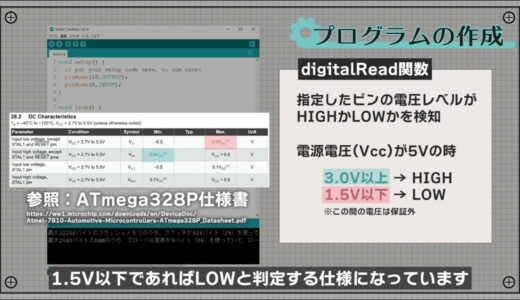
Also, digitalRead is a function that reads whether the voltage level of a specified digital pin is HIGH or LOW.
In terms of specific voltage levels, when the power supply voltage is 5 V, the specification judges the voltage to be HIGH if it is 3.0 V or higher and LOW if it is 1.5 V or lower.
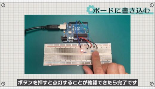
Write on board
Finally, save the file and press the “Write to microcontroller board” button on the toolbar to write the file.
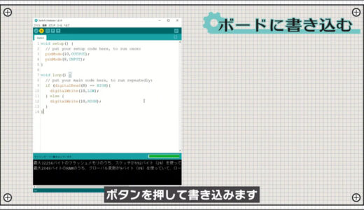
When you confirm that the LED is non-lit when the button is not pressed and lights up when the button is pressed, you are done.
small needlepoint design
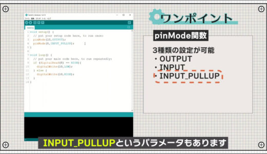
In addition to the OUTPUT and INPUT parameters introduced so far, the pinMode function also has a parameter called INPUT_PULLUP.
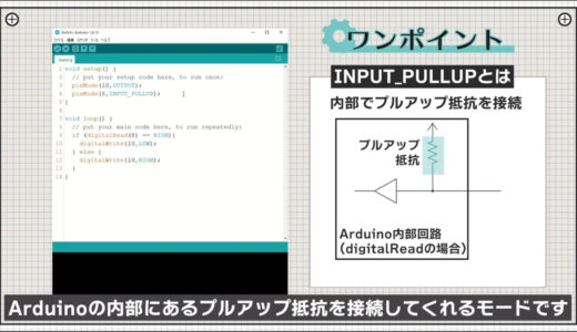
This is the mode that will connect the pull-up resistor inside the Arduino when that pin is set to the input setting.
Therefore, the 10kΩ resistor used in this project is no longer necessary, and the circuit can be cleaned up.
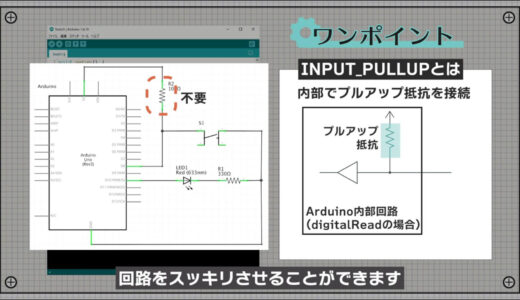
When you want to reduce the circuit size or do not have a resistor at hand, make active use of it.
summary
So, in this issue, we have learned the following
- Usage of the digitalRead function: INPUT,INPUT_PULLUP
- How to use branch processing (if statement): if,else
The rest of this article will be explained in Part 5 of the hands-on introductory course for beginners.
On this site, we post videos and articles that allow you to learn electronics construction systematically from zero, including explanations of the minimum knowledge and tools you need to acquire.

\電子工作歴9年の私のイチ押し!ELEGOOの電子工作キット/