
YouTube
0:00 Opening
0:25 What is an MDS in the first place?
3:05 Points to keep in mind when using transistors
6:21 Points to keep in mind when reading datasheets
8:07 Summary
How to read a parts data sheet


In this issue, I would like to focus on the important points about “how to read data sheets of components that beginners in electronics tend to stumble upon.
Although we use transistors as an example this time, the contents are basically useful for other components as well, so if you have been having trouble understanding how to read data sheets, please refer to this article.
What is a data sheet?
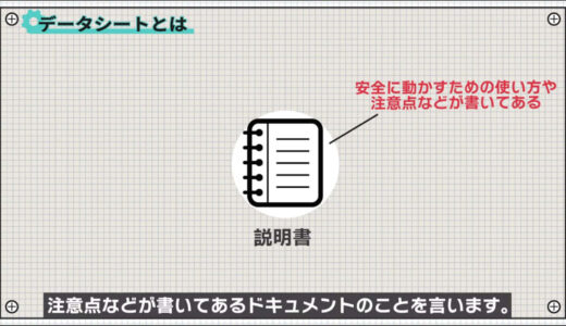
First, let’s talk about what a data sheet is in the first place.
A data sheet is like an instruction manual for a household appliance; it is a document that describes how to use the product and what precautions to take in order to operate it safely.
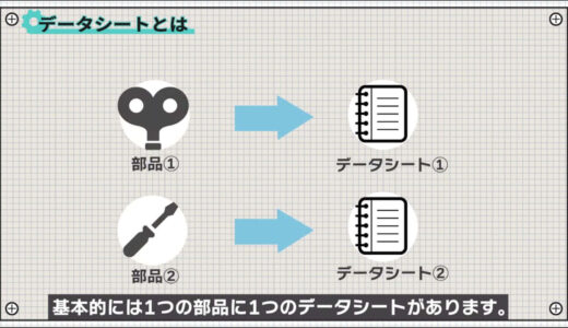
Basically, there is one datasheet per component.
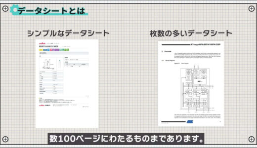
The items listed in a data sheet vary depending on the type of component and can be as simple as a single page or as long as several hundred pages, as in the case of a CPU data sheet.
In addition, there are no specific rules regarding the items to be listed , and there are often differences even among parts of the same type and manufacturer.
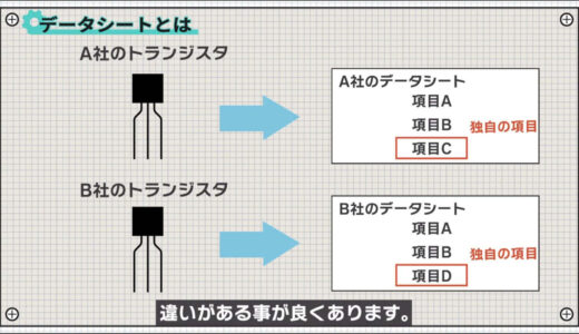
For example, the following images are both transistor datasheets, but as you can see, some items are common and some are different.
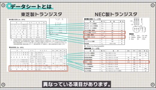
This is because the intended uses are different and the points of appeal are different.
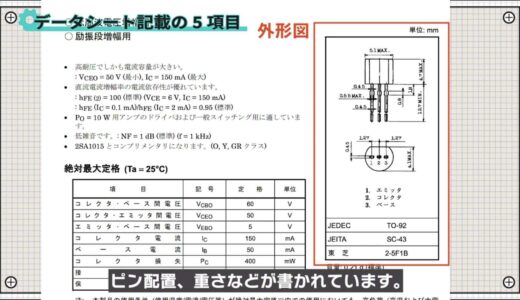
There are five main categories of items listed in the data sheets.
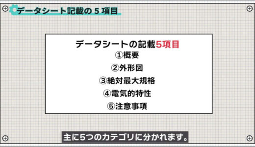
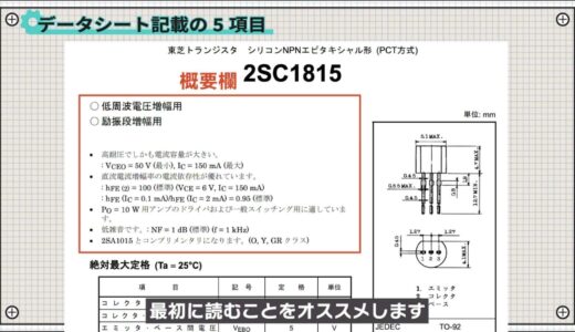
First, the overview describes the applications and strengths of the component.
It is recommended that you read this section first, as it will give you some understanding of the characteristics of the component.
The outline drawing includes package dimensions, pinout, and weight.
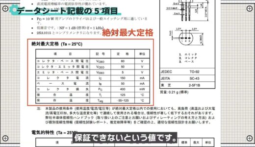
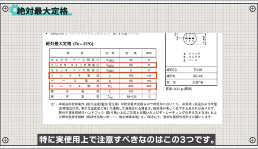
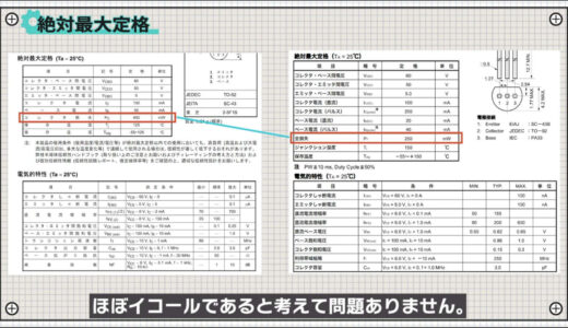
The absolute maximum rating is a value that cannot be guaranteed because it may break if used more than this for even a moment.
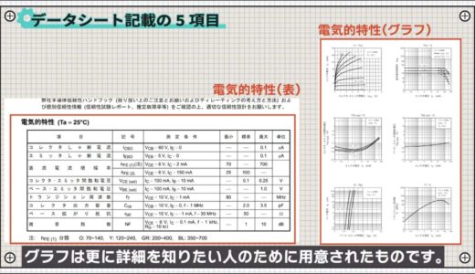
Electrical properties are often divided into tables and graphs.
The table is a summary of typical examples, and the graphs are provided for those who want to know more details.
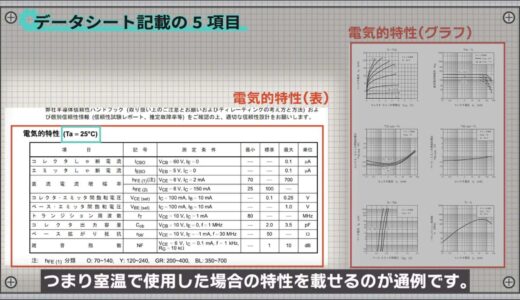
It is customary for the table to include characteristics when used at 25°C, i.e., room temperature.
There is also a minimum, standard, and maximum value, but not all values are listed below.
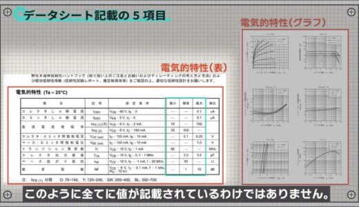
In many cases, the value is included only where it corresponds to this, since the two points that are usually important when using it are where it is and how many worst values it has.
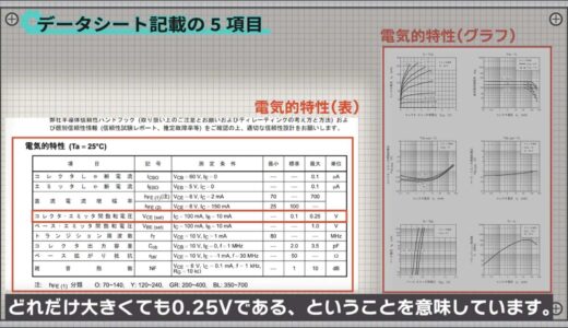
For example, the collector-emitter saturation voltage, which is the voltage that is applied between the collector and emitter when the transistor is turned on, means that it is usually around 0.1V, or 0.25V no matter how large.
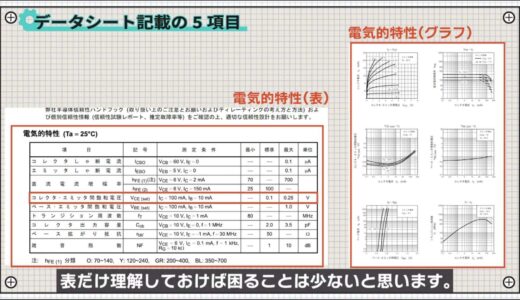
For mass-produced products, elemental and environmental variations are very important, so it is often necessary to read through the graphs, but for personal use, it is basically only necessary to understand the table.
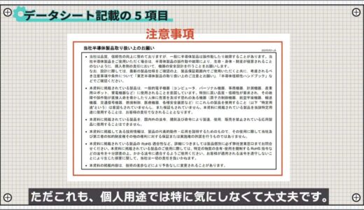
Finally, there are precautions, which are actually quite weighty, such as disclaimers and rights.
Points to keep in mind when using transistors
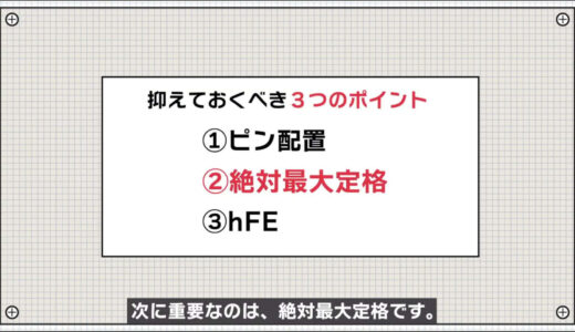
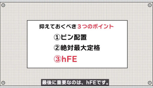
Next, among the many items, here are three points that must be kept in mind when using transistors.
- pin-out
- absolute maximum ratings
- hFE
Although there are many descriptions in the data sheets, in most cases, there is little practical trouble if you check only the three items listed here.
Components such as resistors and coils can be used in either orientation, but many semiconductor components such as transistors have an orientation, so you must always check the pin layout when using them.
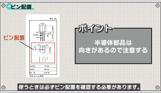
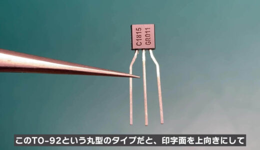
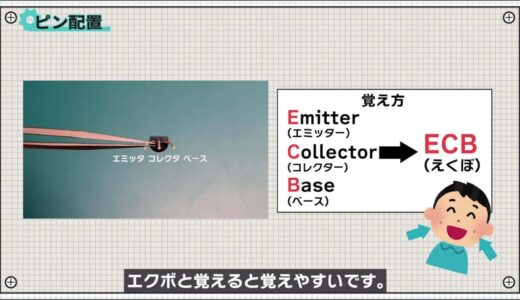
The orientation of the transistor depends on the type of package.In the case of the TO-92, which is a round type, the emitter, collector, and base are aligned from left to right when the printed surface is facing up and viewed from the bottom.
 |
 |
The next most important factor is the absolute maximum rating.
To be honest, all of this information is important because it will help you not to break it, but there are three things in particular that you should pay attention to in actual use, as shown in the following images.
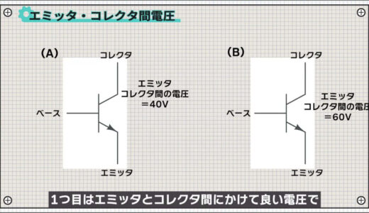
The first is the voltage that may be applied between the emitter and collector, which in the case of this component is 50 V, so a circuit like A, for example, is OK, while B is not.
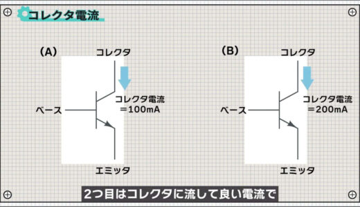
The second is the current allowed to flow to the collector, which in this case is 150 mA, so A is OK and B is NG.
The third is collector loss, which can be calculated by multiplying the collector current by the collector-emitter voltage.
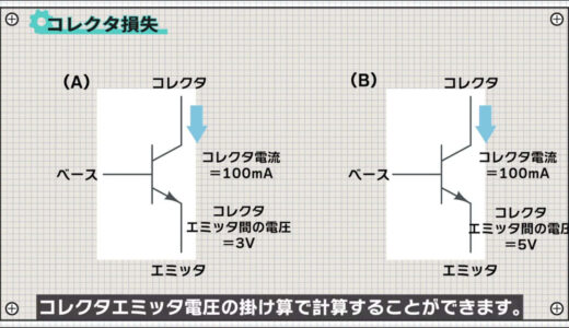
This part is 400mW, so A is OK, B is not.
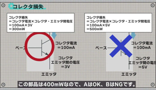
Note that some parts are written as total loss instead of collector loss.
However, this is the difference between including the base loss and not including the base loss, which is negligibly small, so it is safe to assume that the collector loss is almost equal to the total loss.
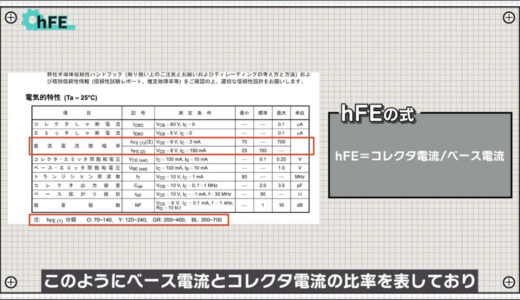
The last important factor is hFE.
hFE is an index of transistor performance and thus represents the ratio of base current to collector current, with higher values indicating higher specifications.
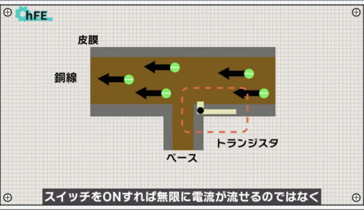
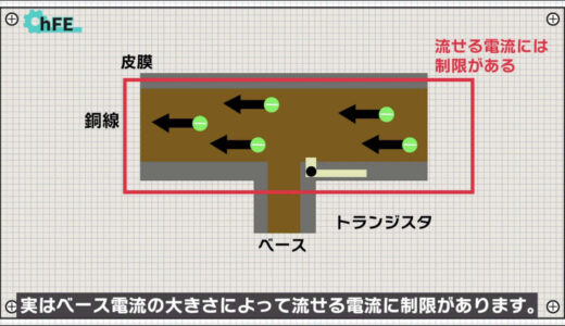
As explained in this video, a transistor has the role of a switch, but turning on the switch does not allow unlimited current flow .
 |
 |
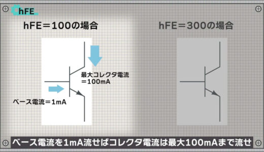
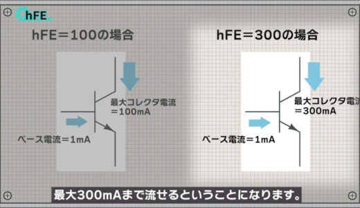
For example, if hFE is 100, the collector current can flow up to 100mA if the base current flows 1mA, and if hFE is 300, the collector current can flow up to 300mA.
 |
 |
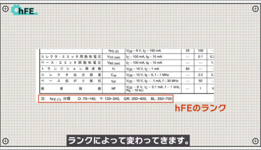
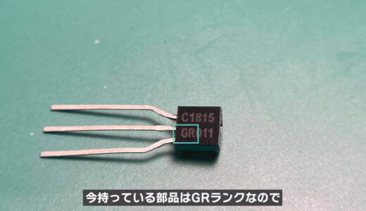
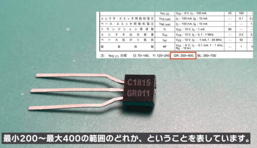
The rank is indicated on the model name and on the printed side, and since the part you have now is GR rank, it means that it is one of the range of 200 minimum to 400 maximum.
 |
 |
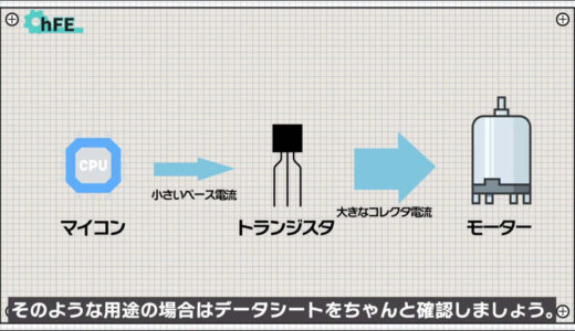
hFE is a bottleneck when base current is drawn from a small output current like a microcontroller board and a large collector current is required like a motor, so check the datasheet properly for such applications.
I think we need not worry about most of the other items mentioned here.
As long as it is properly mounted on the board, heat will escape through the board.
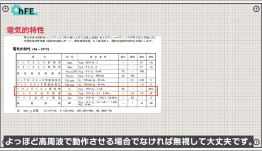
Also, the transition frequency and collector output capacitance can be ignored unless the device is to be operated at a very high frequency.
Notes on reading datasheets
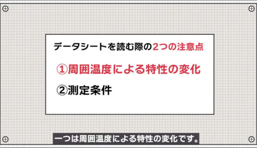
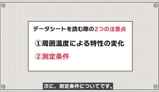
Finally, two points to keep in mind when reading the datasheet are explained below.
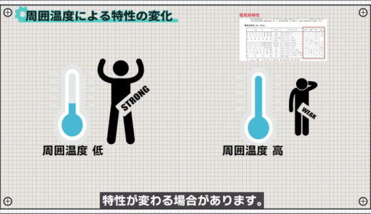
One is the change in characteristics with ambient temperature.
The values in the table of electrical characteristics are only the characteristics at room temperature, and the characteristics may change as the ambient temperature rises due to heat generation, etc.
For example, the following figureThe graph in Figure 3.1 shows the variation of allowable collector loss with temperature.
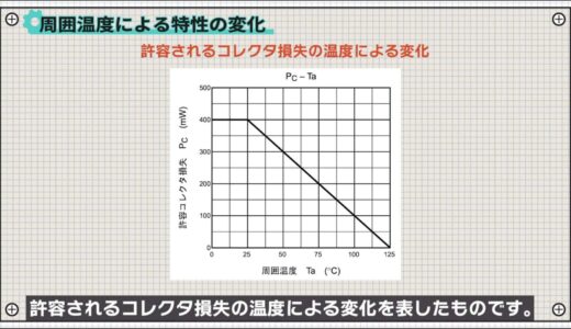
When used at 25°C, it can hold up to 400 mW as stated in the maximum rating, but when used at 75°C, it can actually only withstand up to 200 mW.
Next, we discuss the measurement conditions.
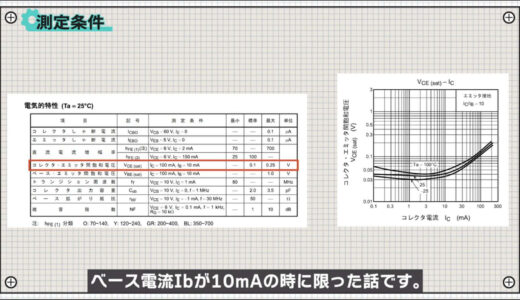
Tables and graphs of electrical characteristics are always accompanied by measurement conditions.
This is because the results will vary depending on the measurement conditions.
For example, the standard collector-emitter saturation voltage is 0.1 V in the table, but this is only when the collector current Ic is 100 mA and the base current Ib is 10 mA.
The following graph shows the saturation voltage between collector and emitter when the ratio of collector current to base current is 10. You can see that the values are very different, such as 0. 04V when the collector current is 10mA and the base current is 1mA.
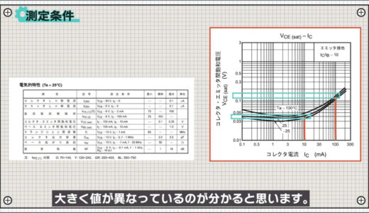
So, don’t just rely on the values in the table, but also pay attention to the measurement conditions when designing details.
summary
In this issue, we have focused on the important points about how to read parts sheets, which are often a stumbling block for beginners in electronics construction.
If you keep in mind what we have discussed here and look at some data sheets, you will find it interesting to see the subtle differences between components and manufacturers.
If you have time, you might want to take a look.
On this site, we post videos and articles that allow you to learn electronics construction systematically from zero, including explanations of the minimum knowledge and tools you need to acquire.

\電子工作歴9年の私のイチ押し!ELEGOOの電子工作キット/