
YouTube
0:00 Opening
0:18 Demonstration of actual equipment
0:38 setting a question (for an exam)
1:10 What is a biometric sensor?
2:25 Four filters to remove noise
3:54 Notch filter to remove specific frequencies
4:59 How to check filter characteristics with AC analysis
5:50 Summary.
Four filters to remove noise


For those who are interested in this topic, we will discuss four basic noise filters under the theme of “various ways to remove noise from sensors.
Please read this article to the end to understand the characteristics of each type of noise filter and how to remove noise.
This information is also explained in the QC Publishing newsletter, so please take a look at that as well.
Demonstration of actual equipment
The following image shows a servo motor that moves in accordance with the force applied to the hand using a myoelectric potential sensor, one of the biometric sensors.
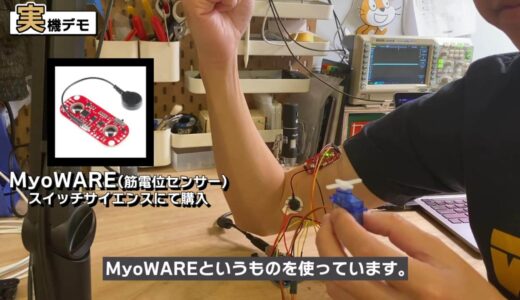
The sensor is called “MyoWARE” purchased from Switch Science.
It can also be applied to remote-control gadgets by sending signals via the Internet.
question (e.g. on a test)
Suddenly, here is the problem.
Which of the following is the frequency response of this circuit from a to d?
Consider the following diagram.
(1) a (2) b (3) c (4) d
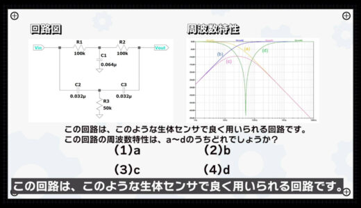
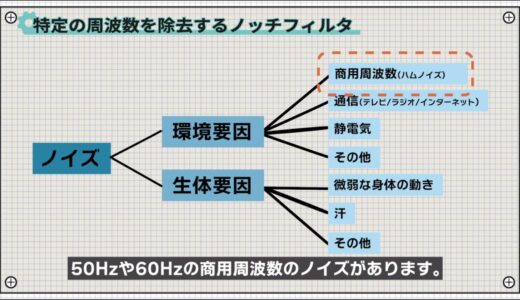
One of them is electromagnetic noise due to commercial frequencies such as 50 Hz and 60 Hz.
Now for the solution.
*Press the answer tab below to get the answer.
What is a biometric sensor? What is a body sensor?
First of all, let’s talk about what a biometric sensor is in the first place.
When we want to know the internal state of our own body, we cannot directly implant sensors, so we need to infer the inside using information accessible from the outside of the body.
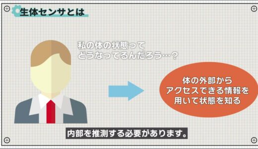
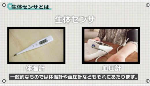
Biometric sensors are used in such cases, and common examples include thermometers and blood pressure monitors.
These are relatively easy to obtain information, but electrical signals generated when muscles contract, called myopotentials, for example, are difficult to detect because the signals are weak.
Here is a measurement of arm muscles using the “MyoWare” myopotential sensor.
As shown in the following image, the voltage increases as power is applied.
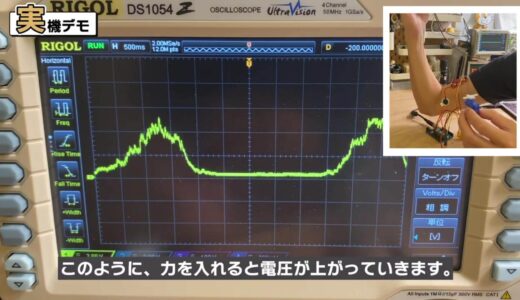
By reading this voltage value and operating according to the value, a kind of remote control gadget can be created.
Although muscle information appears to be easily acquired, in fact, the voltage levels originally generated are only a few 100uV to a few mV.
The following sensor module has a built-in circuit that amplifies about 1000 times with an operational amplifier.
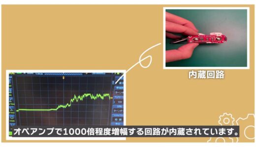
At this time, since the original voltage level is low, various noises come on board as shown in the following image , which is a major concern when dealing with biometric sensors.
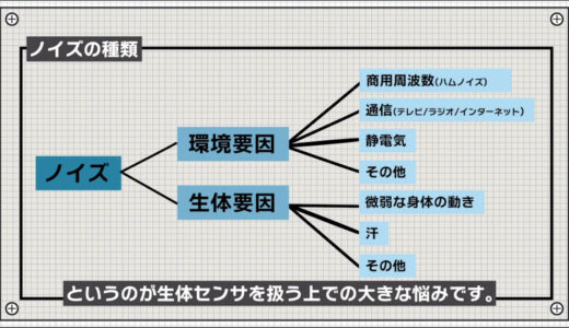
If these are not removed first, the noise will be amplified together.
Four filters to remove noise
This is where noise filters come in.
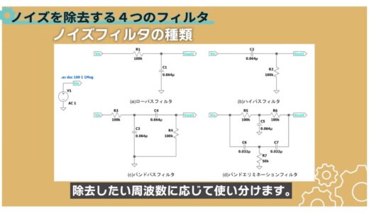
Four types of noise filters are presented here.
There are four main types of noise filters, as shown below, and they are used according to the frequencies to be removed.
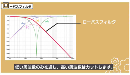
- low pass filter
- HPF
- Band-Pass Filter
- band elimination filter
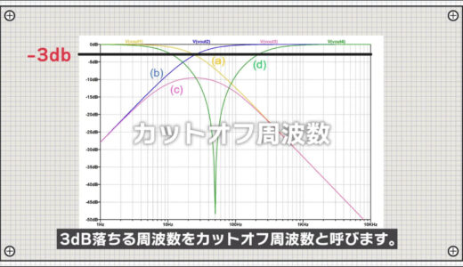
When the input is Vin and the output is Vout, the frequency response of the Vout/Vin relationship plotted by frequency is shown in the following figure, which was explained earlier in the problem.
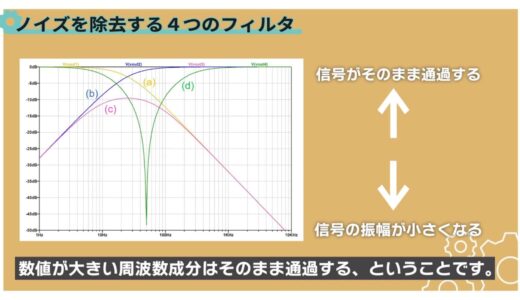
What the frequency response means is that frequency components with smaller values on the vertical axis become smaller, while frequency components with larger values pass through unchanged.
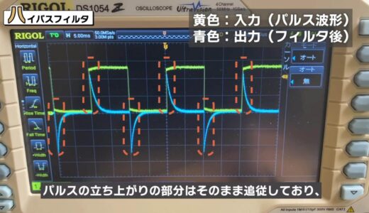
If we take the actual pulse waveform as input and look at the output side, we see a waveform with a slow rising edge as shown here.

The reason why the waveform has a dull rising edge is because the rising edge changes quickly in time and the components in that part of the waveform are cut off.
On the other hand, the high-pass filter has the exact opposite characteristics of the low-pass filter: it follows the rising part of the pulse as it is, and the voltage drops when the pulse becomes stable.
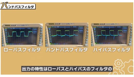
In addition, since a bandpass filter is a circuit that is a cross between a low-pass filter and a high-pass filter, the output characteristic is a waveform that is between the low-pass and high-pass filters.
The frequency at which the frequency characteristic drops by 3 dB is called the “cutoff frequency.
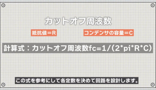
The cutoff frequency can be calculated using the following formula. If the frequency to be cut has been determined, design the circuit by determining each constant with reference to the following formula.
(*When resistance is R and capacitance of capacitor is C)
Notch filter to remove specific frequencies
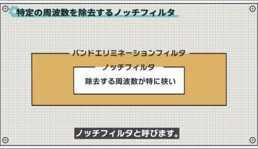
And finally, we introduce a slightly special notch filter.
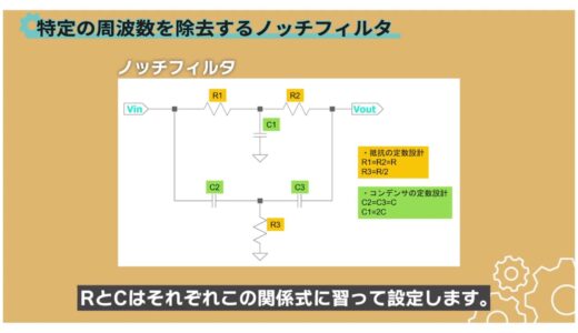
Among band-elimination filters, a filter with a particularly narrow frequency to be removed is called a notch filter.
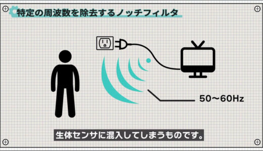
One type of noise that rides on biological sensors is 50 Hz and 60 Hz commercial frequency noise, called hum noise.
This is something that our body itself becomes an antenna and gets mixed in with our biological sensors.
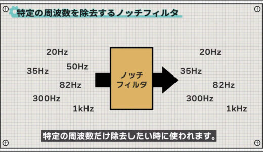
Notch filters are used when you want to remove only certain frequencies, as in the following image.
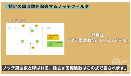
The notch filter has the following form, and R and C are set by learning from this relationship, respectively.
When R and C are set according to this relationship, the frequency to be removed, called the “notch frequency,” is expressed by the following equation.
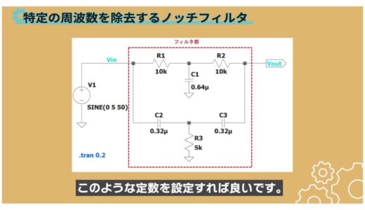
For example, to set the notch frequency to 50 Hz, you can set the constants as shown in the following image.
How to check filter characteristics with AC analysis
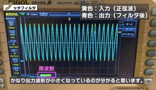
Let’s check the actual waveforms here, too.
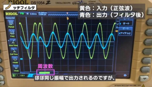
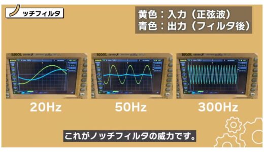
If you input a sine wave and change the frequency in this way, you will see that the output has almost the same amplitude at low and high frequencies, but the output waveform is much smaller around 50 Hz.
 |
 |
This is the power of the notch filter.
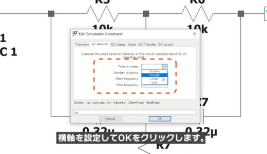
When you want to see differences in behavior at different frequencies, such as the frequency response of a filter, it is easier to check by setting the horizontal axis to the “frequency axis” instead of the “time axis.
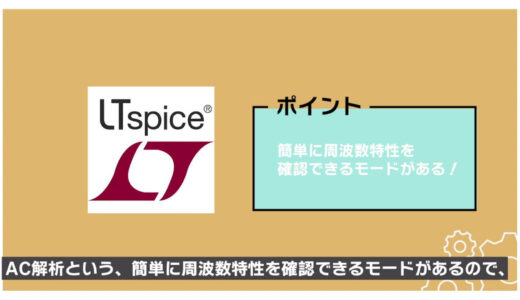
LTspice, a free circuit simulation software, has a mode called “AC Analysis” that allows you to easily check the frequency response, which is important to remember here.
The following is a brief explanation of how to use AC analysis.
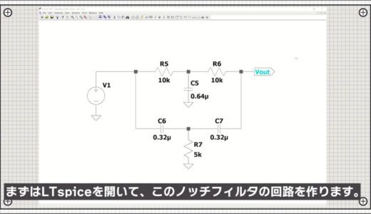
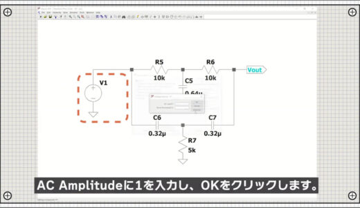
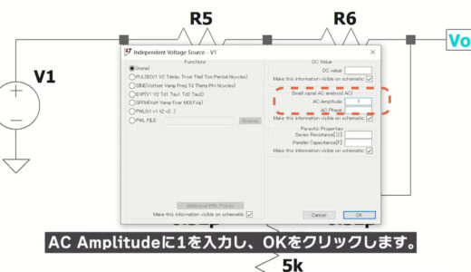
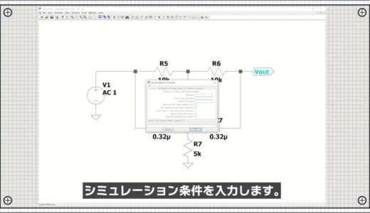
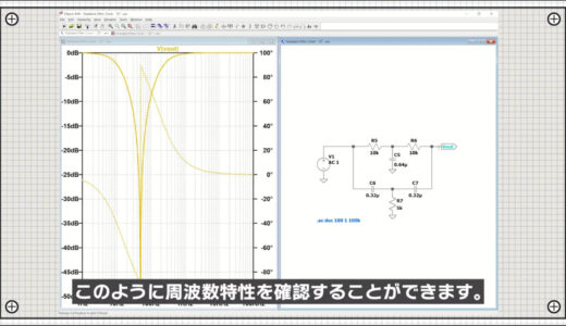
This is a brief description of how to use AC analysis.
summary
In this issue, we have introduced four basic filters under the theme of “various ways to remove sensor noise.
If you can use these four, you will have a fairly wide range of applications, so be sure to keep them in mind.

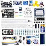
\電子工作歴9年の私のイチ押し!ELEGOOの電子工作キット/