YouTube
0:00 Opening
0:16 Demonstration of actual equipment using DC brush motors
0:51 Issue.
1:19 Role of Diodes
4:12 Simulation with H-bridge circuit
5:44 Summary.
How to use brushed DC motors safely


In this issue, we will talk about ” Using Brushed DC Motors Safely ” for those who want to learn how to use them.
This time, we will talk about the theme of “how to use brushed DC motors safely” for such people.
Please read this article to the end, as it will deepen your knowledge of how motors work and the role of diodes, and enable you to use DC motors safely.
The content of this video is also explained in the CQ Publishing newsletter, so please take a look at that as well.
Demonstration of actual equipment using DC brush motors
First, before I get into the main subject, I would like to show you a gadget that uses a brushed DC motor, which is the subject of this issue.
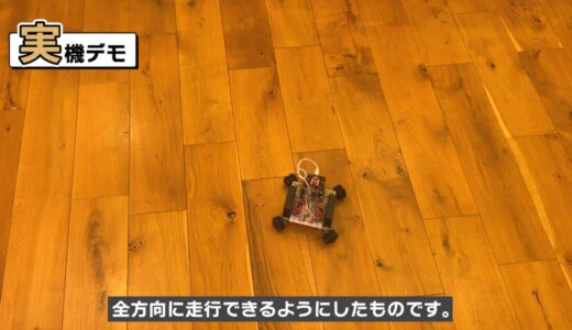
This gadget combines a special wheel called an omniwheelwith a driver IC capable of bidirectional control of a brushed DC motor, enabling it to run in all directions.
The gadget is connected to the PC via Bluetooth and is moved by giving running instructions from “Scratch” on the PC screen.

Brushed DC motors are simple motors that have been around for a long time, but there are still many ways to play with them depending on how they are used.
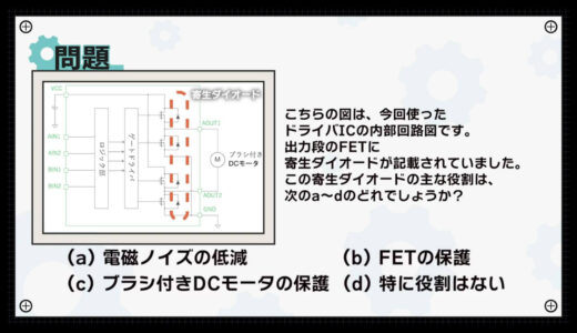
question (e.g. on a test)
Suddenly, here is the problem.
Which of the following (a)-(d) is the primary role of this parasitic diode?
(a) Reduction of electromagnetic noise (b) Protection of FETs (c) Protection of brushed DC motors (d) No specific role.
Now for the solution.
*Press the answer tab below to get the answer.
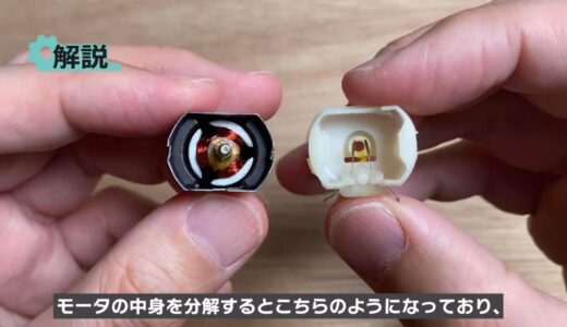
The following is a step-by-step explanation.
Disassembling the contents of the motor, it consists of the following image and picture.
 |
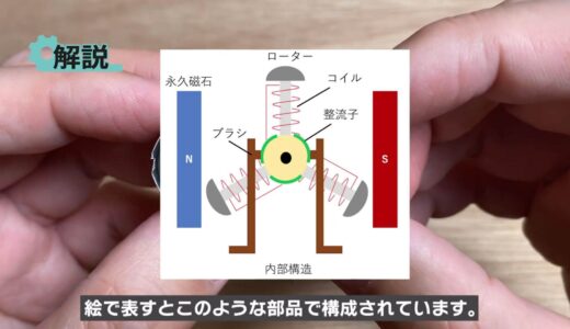 |
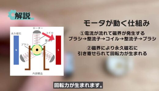
A coil is wound around the rotor, and a magnetic field is generated in the rotor when current flows through the route of “brush→ commutator→ coil→ commutator→ brush”.
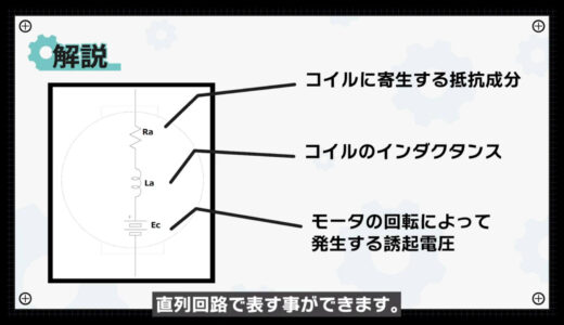
And this motor can be represented by the following simple circuit, which is a series circuit of “inductance of the coil,” “resistance component,” and “induced voltage generated by the rotation of the motor.
Role of Diodes
Let’s take a moment to review the role of the diode with this circuit.
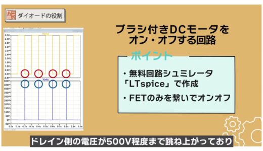
The following circuit was created to turn a brushed DC motor on and off using the free circuit simulator LTspice.
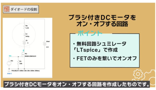
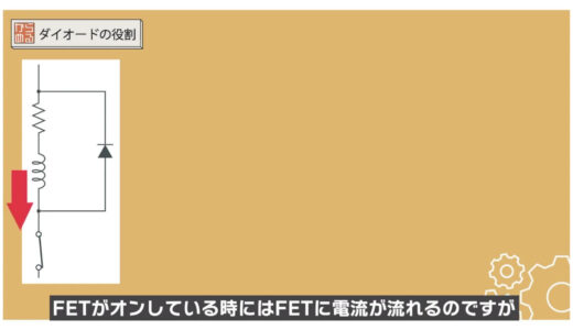
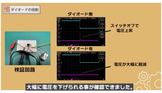
First, here we simply connect only the FETs and turn them on and off.
If you run a simulation with this, you will see that the voltage on the drain side jumps up to about 500V at the moment the FET turns off, as shown in the following results, indicating that a significant voltage is applied.
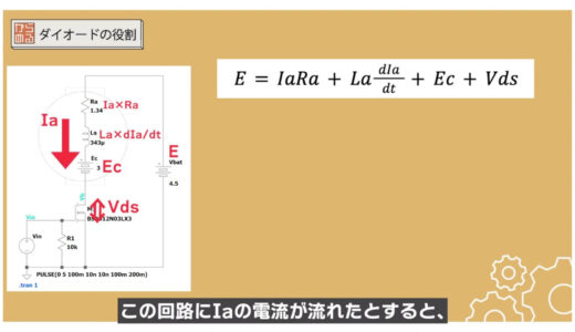
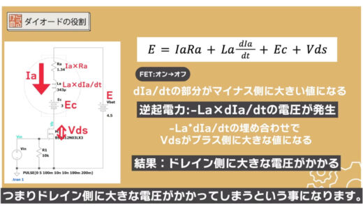
This phenomenon can be explained by the following equation.
If a current of Ia flows in this circuit, the voltage of each part added together is equal to the supply voltage E, which can be expressed by the previous equation.
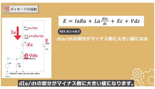
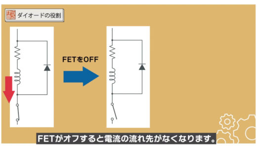
When the FET is turned off from on, the dIa/dt part becomes a large value on the minus side because the current suddenly becomes small.
The result is a large voltage of “-La*dIa/dt” called the back EMF.
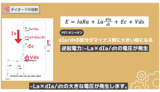
Since the sum of the voltages of each part must be equal to the supply voltage, Vds becomes a large value on the positive side to compensate for the back EMF, resulting in a large voltage on the drain side.
Note that using components with low withstand voltage between drain and source may destroy the FET!
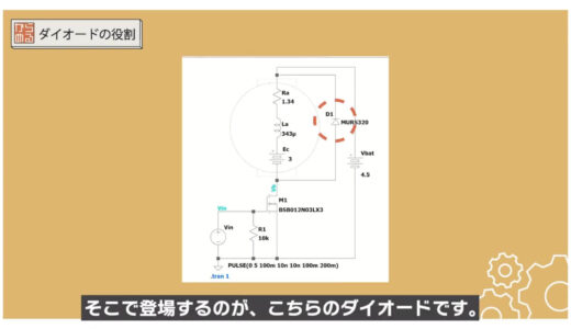
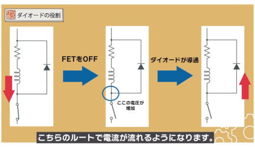
This is where the following diodes come in.
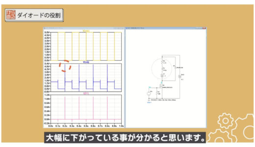
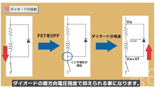
If you run the simulation, you will see that the voltage on the drain side at the moment the FET is turned off is about several V, which is a significant drop.
If you look at where the current that caused the voltage jump in the previous example went, you can see that it flowed out through the diode as shown below.
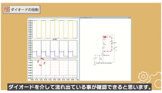
This flow of current through the diode is explained in detail in the following diagram.
When tested in an actual circuit, it was still confirmed that the voltage could be significantly reduced by adding a diode.
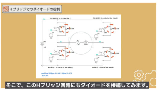
This circuit is also called an H-bridge. As shown in the following image, four FETs are turned on and off in a passive manner to change the direction of the current flowing to the motor, thereby achieving bidirectional operation.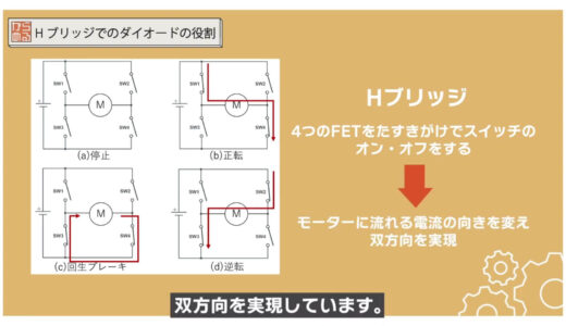
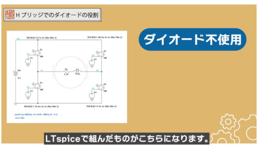
This circuit, assembled in LTspice without diodes, is shown in the figure below.
Instead of FETs, we use switches that exist only in the simulation, called voltage-controlled switches.
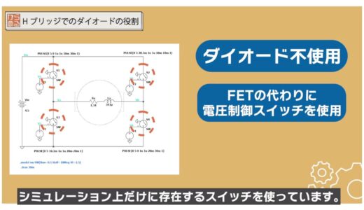
Since it takes a little time to turn the high-side FETs on and off, this item is useful for simple operation verification like this one.
Running the simulation, we can see that the drain voltage fluctuates significantly at the moment the FET is turned off, as shown in the figure below.
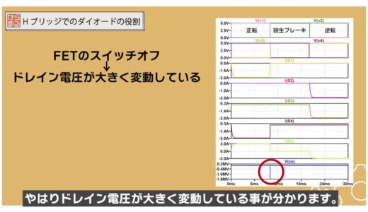
The value is negative because the direction of the current is different from the previous example, and the value is unrealistic because a voltage-controlled switch is used. However, the fact remains that a large voltage is being applied to the switching device.
Simulation with H-bridge circuit
So, we will also connect a diode to this H-bridge circuit.
The following figure shows the result. The diode greatly reduced the drain voltage sink.

And as in the previous example, we can see that current flows through the diode at the moment it is turned off.
Thus, by connecting a diode, the current is bypassed and the FET is protected by suppressing sudden changes in voltage.
summary
In this issue, we have taken the subject of brushed DC motors, which are commonly used in electronic construction, and have shown how to use them safely with diodes.
Be sure to use a set of diodes to avoid breaking the switching elements.

\電子工作歴9年の私のイチ押し!ELEGOOの電子工作キット/