
YouTube
0:00 Opening
0:22 What is a power pin?
1:20 Characteristics of the two types of power supplies
3:14 Demonstration of actual equipment
4:13 One Point Advice
4:38 Summary.
Two Power Supply Methods Learned from Microcontroller Board Power Supply Pins|Introduction to Practical Electronic Circuits with LTspice


For those who want to learn more about power supply methods, we will talk about ” two power supply methods learned from microcontroller board power supply pins “.
This article will give you a better understanding of the characteristics of linear and switching systems, so please read it all the way through.
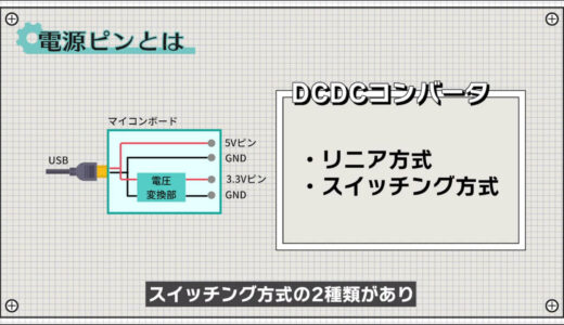
What is a power pin?
Let us begin with a brief description of the power supply pins.
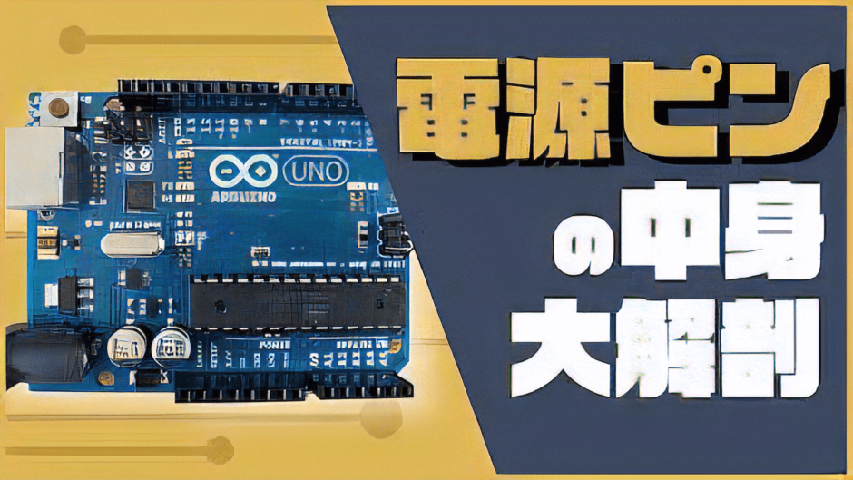
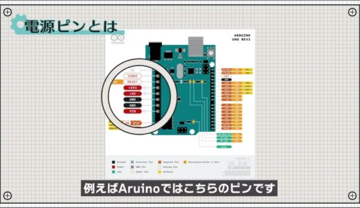
What we call power pins here are the pins in the I/O pins of the microcontroller board that supply power such as 5V or 3.3V.
For example, in Aruino, the area indicated by the zeros in the following image is the pin.
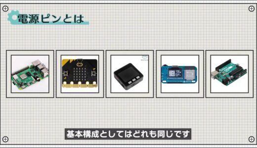
There are several types of microcontroller boards as shown below, but they all have the same basic configuration.
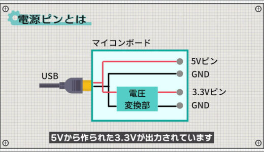
First, 5V is supplied to the microcontroller board via USB and output directly from the 5V pin.
For the 3.3V pin, 3.3V made from 5V is output via a voltage converter.
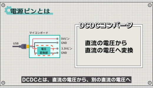
The voltage conversion part here is technically called a DCDC converter.
Two power supply methods
In fact, there are two types of DCDC converter methods: linear and switching, each with different characteristics.
Let us introduce the two power supply methods.
linear system
The first power supply method is the “linear method.
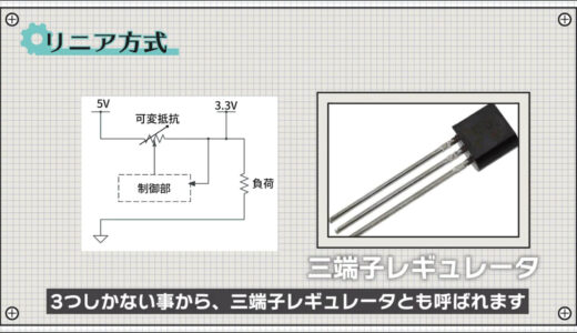
The operation and use of the above regulator is very simple, and it is also called a “three-terminal regulator” because it has only three component terminals.
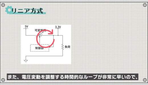
It also has the advantage of a very fast time loop to adjust for voltage fluctuations, making it easier to stabilize the voltage.
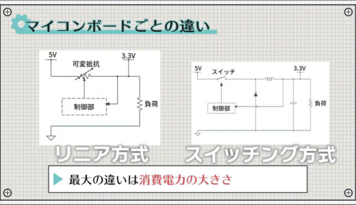
On the other hand, there are also linear regulators, which regulate voltage by converting power into heat and releasing energy, as shown in the figure below.
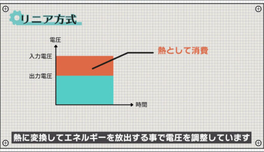
This has the disadvantage that it tends to generate heat and cannot carry a large current.
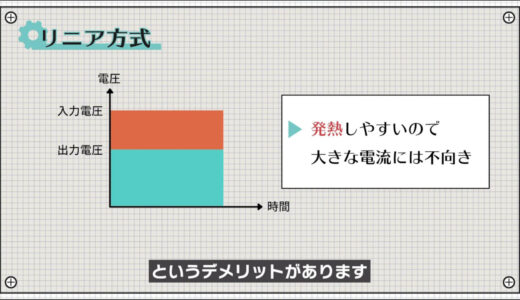
The linear method can be summarized as follows
- Simple operation and easy to use
- Small voltage fluctuations
- High power consumption
switching regime
The second power supply method is the “switching method.
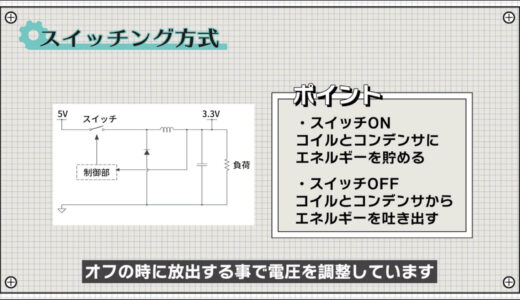
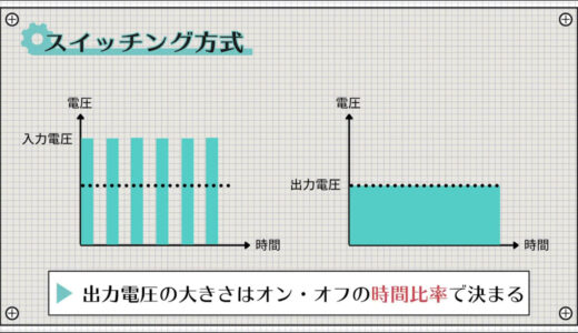
The operation is somewhat more complicated than the linear method, but simply put, the voltage is regulated by storing energy in a capacitor when the switch is on and releasing it when the switch is off.
The magnitude of the output voltage can be changed by this on/off time ratio.
Unlike the linear method, the switching method has the advantage of low power consumption because it converts voltage by changing the form of energy rather than consuming energy.
On the other hand, the disadvantages are that a large number of components are required and that voltage fluctuations are large.
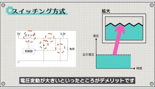
The switching method can be summarized as follows
- Low power consumption
- Large number of parts
- Large voltage fluctuations
The following image shows a table summarizing how the 3.3V outputs of recently popular microcontroller boards are made.
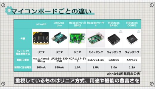
As a conclusion, it seems that the linear method is used for boards with limited applications or those that emphasize miniaturization , while the switching method is used for boards that appeal to a wide range of applications and functions.
Thus, both methods are prevalent in the world and are used by the right people at the right time.
The biggest difference between these two methods is their power consumption.
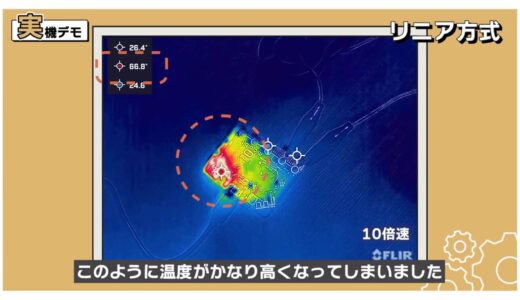
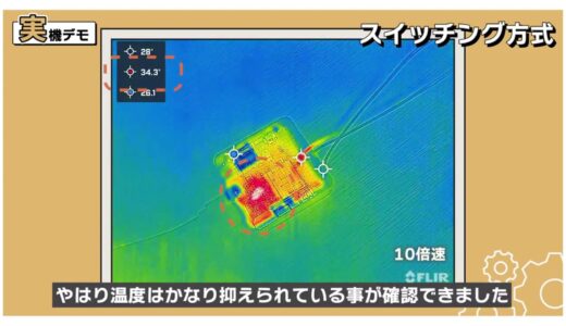
So, finally, let’s connect the loads and see how much the heat actually differs between each method.
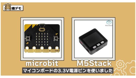
As for the load, the ultrasonic atomizing module commonly used in humidifiers was just right for the size of the load, so we connected this to monitor the temperature.
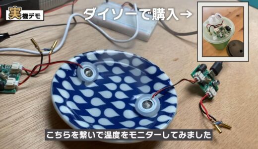
The load of the ultrasonic atomizing module is about 5 to 10 ohms in terms of resistance value. approximately 5 to 10 ohms resistance equivalent.
When I first connected the microbit with the linear method, the temperature became much higher as shown here.
On the other hand, with the M5Stack, which is a switching system, we were still able to confirm that temperatures were considerably suppressed.
So, on the subject of microcontroller board power supply pins, we introduced two power supply methods and their characteristics.
The actual difference in power values is explained in the CQ Publishing newsletter, so please refer to that for the rest of the article.
advice of a point (advice that may be helpful to some people)
In addition, I would like to offer one final piece of advice.
Although the microcontroller board is connected for demonstration purposes, it is basically not designed to supply a large current, so it is safer not to connect a large load such as a motor or ultrasonic spraying module.
summary
In this issue, we dissected the contents of the power supply pins on a microcontroller board.
Using LTspice, you can easily simulate operation and power consumption, so if you are “afraid of moving things around,” please make use of that as well.

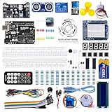
\電子工作歴9年の私のイチ押し!ELEGOOの電子工作キット/