
YouTube
0:00 Opening
0 :19 Basic Rules of Schematics
2 :23 Minimum Circuit Symbols to Remember
4 :10 Tips for Reading Schematics
5 :16 Summary
How to read a schematic diagram that you don’t have to be an electrician to understand.


I recently took a survey on Twitter and found that quite a few people are struggling with “how to read a schematic “.
Therefore, I would like to talk about the theme of “how to read a schematic diagram that you don’t have to be an electrician to understand.
Please read this article to the end so that you can understand the basic rules of schematics and be able to read schematics.
Basic Schematic Rules
First, we will discuss the basic rules of schematics that you should at least know.
There are no absolute rules for schematics, but there are some conventions that should be easy to read for everyone.
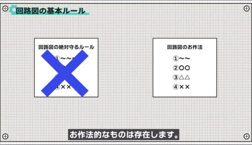
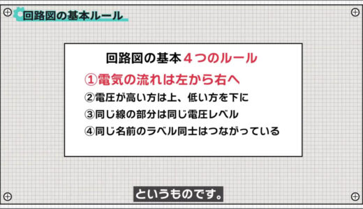
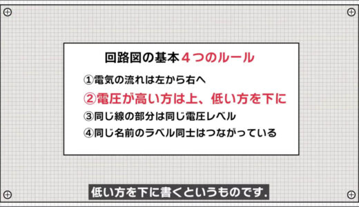
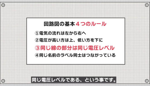
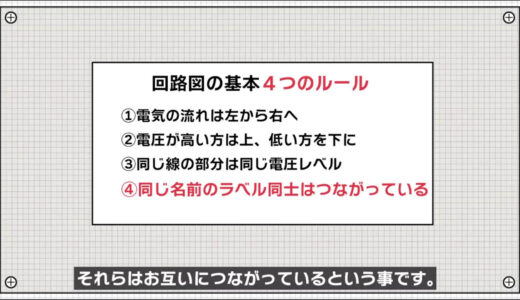
There are four manners, roughly speaking, as follows.
- Electricity flows from left to right
- The higher voltage is up, the lower voltage is down.
- Same line section has the same voltage level
- Labels with the same name are connected to each other.
The following are examples of publicly available Arduino schematics, one at a time.
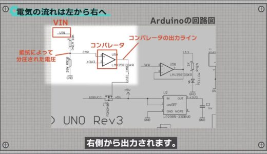
The first is that “electricity flows roughly from left to right.
For example, in the following image, the supply voltage VIN is input on the left side, and the voltage divided by the resistor enters the comparator and is output on the right side.
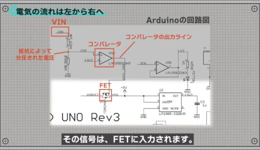
The signal is then input to the FET.
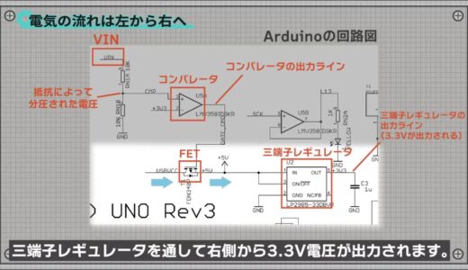
The FET part also has a signal input from the left side, which is transmitted to the right side when the FET turns on, and a 3.3V voltage is output from the right side through the three-terminal regulator.
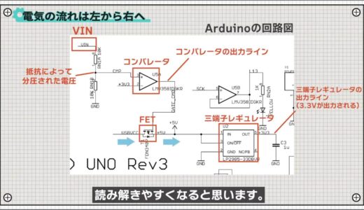
Although a quick glance at a schematic will not tell you the direction of current, it will be easier to read and understand if you keep this basic gesture in mind.
The next one is “write the higher voltage at the top and the lower voltage at the bottom.
Voltage is often compared to a dam, so this image is easy to understand.
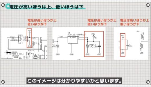
As you can see from the schematic, in many places the voltage was written on top.
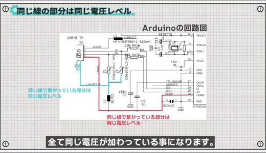
The next thing is that “parts connected by the same wire are at the same voltage level.
For example, since they are connected to each other in this section, they will all have the same voltage applied to them.
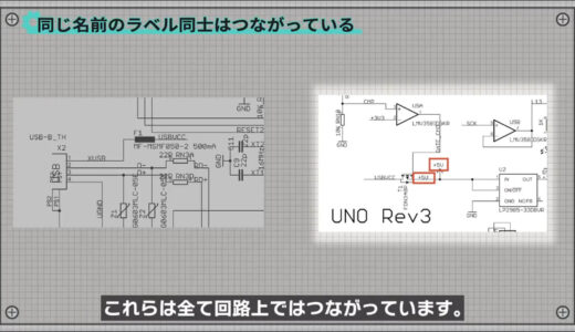
The last is that “if power, GND, and label have the same name, they are connected to each other.
For example, the circuit diagram below shows many power supplies named +5V, all of which are connected in the circuit.
In the following image, there is also a signal with the same name, USBVCC, and these are actually connected as well, although they are far apart on the schematic.
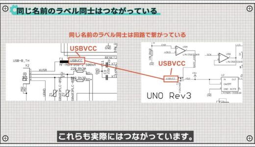
This is done to reduce the number of lines as much as possible to avoid messing up the schematic.
Minimum circuit symbols to memorize
Next, here are the minimum circuit symbols to remember.
If you memorize the circuit symbols in advance, it will be much easier to read the circuit diagrams, so keep them in mind here.
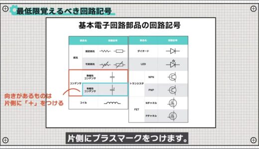
First, the following image shows the circuit symbols for the very basic electronic components.

The resistance is equally used by these jagged or square ones.
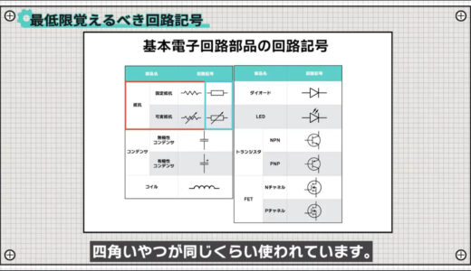
Capacitors with an orientation type, such as electrolytic capacitors, should have a plus mark on one side.
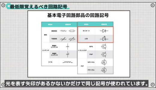
Since diodes and LEDs have the same element structure, they use the same symbols only with or without arrows to represent light.
There are two types of transistors and FETs, each differing only in the direction of the arrow.
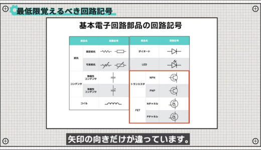
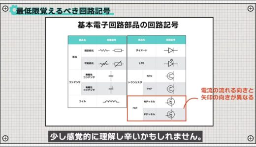
Transistors are easy to remember because the direction of current flow corresponds to the direction of the arrow, but FETs may be a little harder to understand sensibly because they represent the direction of parasitic diodes that are created in the device due to its structure.
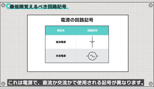
The images below are power supplies, with different symbols used depending on whether they are DC or AC.
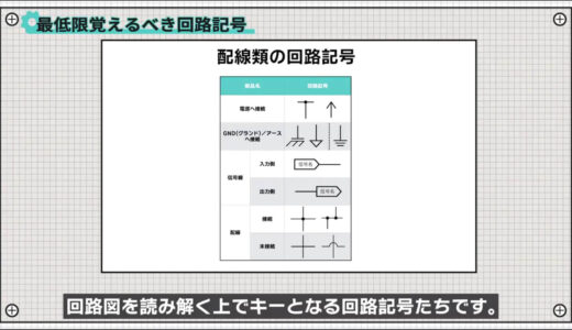
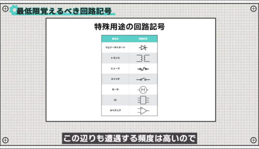
The following images show the key circuit symbols circuit symbols that are key to deciphering schematics.
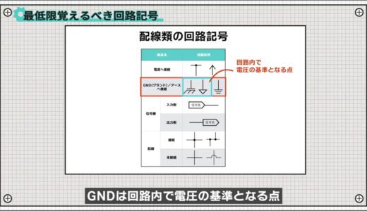
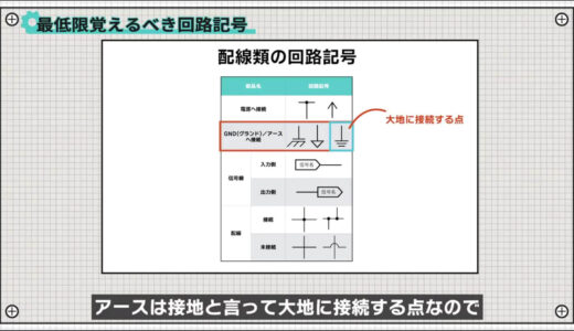
GND and ground are sometimes used without distinction, but they have strictly different meanings, sinceGND is a voltage reference point in a circuit andground is a connection point to the earth.
 |
 |
Signal lines are used to connect distant locations on a circuit diagram.
The direction of the arrows matches the direction of the inputs and outputs, making them easy to read and understand.

For wiring, black circles are to be placed where wires are connected to each other.

Incidentally, it is said that a good schematic is to avoid making a cross because the presence or absence of a black circle can be difficult to recognize.
And finally, we also include parts for special applications.
Tips for reading schematics
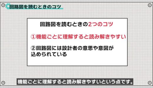
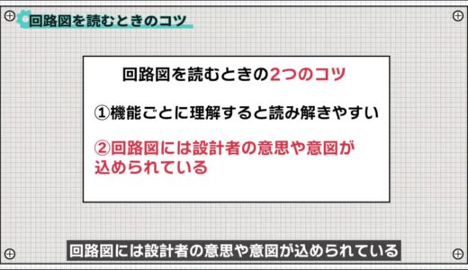
Finally, just two little tips for reading schematics.
- Easy to read and understand by function.
- Schematics contain the designer’s intentions and intent.
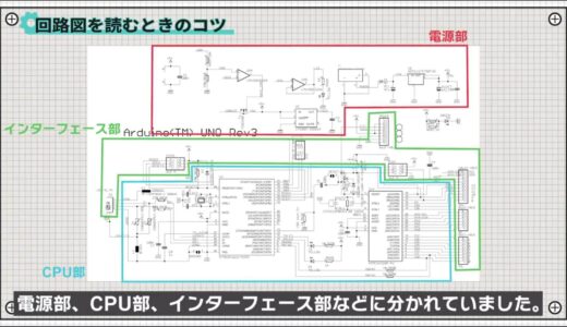
The first point is that schematics are often written in a function-by-function format to some extent, so they are easier to read and understand when understood function by function.
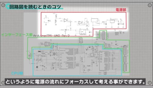
This Arduino schematic was divided into a power supply section, CPU section, interface section, and so on.
So, for example, if we look at the power supply section, we can focus on the flow of the power supply, such as how many volts are created based on which voltage.
Second, schematics contain the will and intention of the designer.
One of the reasons for this is that after drawing a schematic, the designer then moves on to board layout and pattern design, at which time the designer refers to the information on the schematic.

For example, crystals, which are the heart of the CPU, and capacitors, which are used for stable operation, should be placed near the CPU, so they are often drawn near the CPU in the circuit diagram.
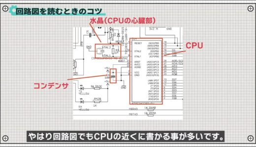
Thus, if we keep in mind that schematics are not just a drawing, we can step up to another level of deeper understanding.
summary
In this issue, we have talked about “How to Read a Circuit Diagram You Don’t Have to Be an Electrician to Understand”.
There may be a lot to remember at first, but there are generally a limited number of circuit symbols that you will encounter, so let’s start with just the symbols introduced here.
If you want to see and study a lot of schematics, CQ Publishing’s newsletter is a good place to start.
This site also provides other videos and articles to help beginners learn electronics construction systematically from zero, including explanations of the minimum knowledge and tools they need to acquire.
\電子工作歴9年の私のイチ押し!ELEGOOの電子工作キット/