YouTube
0:00 Opening
0:17 What is chattering?
1:23 Issue.
2:11 How to reproduce measured voltage waveforms in LTspice
4:24 How to remove chatter
6:13 Chattering Removal Using RS Flip-Flops
7:02 Summary.
Be careful of chattering when turning switches on and off


In this article, we will discuss the topic ” Be careful of chatter when turning on and off switches.
Please read this article to the end to understand how chattering occurs and to learn more about the countermeasure circuit.
The content of this video is also explained in the CQ Publishing newsletter, so please take a look at that as well.
What is Chattering?
First, let us explain what chatter is.
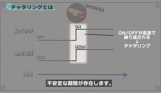
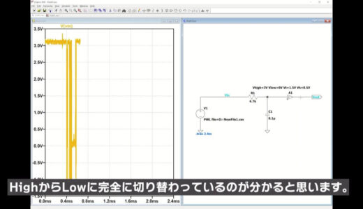
Switches are common components used in any product, and ideally, voltage values are expected to switch neatly between High and Low according to the OFF/ON state of the switch.
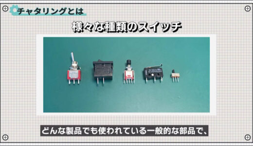
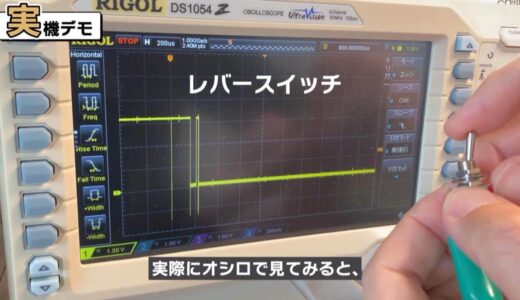
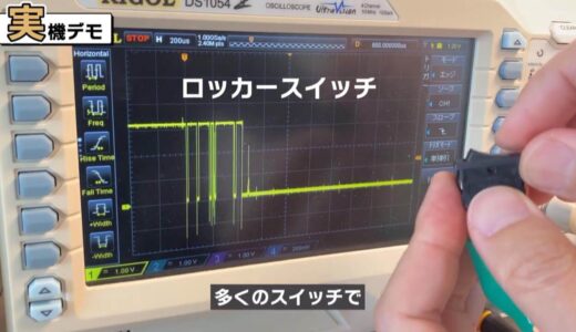
However, at the moment when the switch actually switches, there is a period of instability called chattering, in which ON/OFF is repeated at high speed.
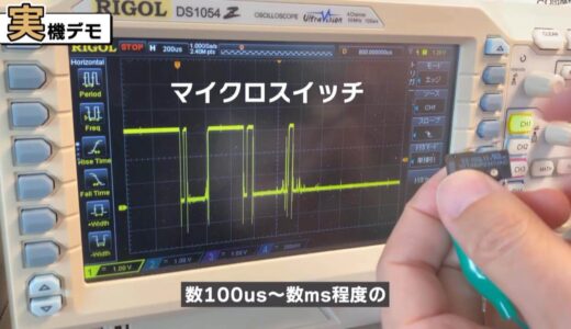
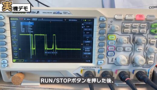
When we actually looked at the oscilloscope, we observed a chattering period of several hundred us to several ms for many switches, depending on the type of switch.
 |
 |
 |
The cause of this chattering can be understood by taking apart the contents of the switch.
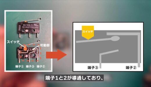
The following image shows a switch called a microswitch, which is often used in mice.
A magnified view of the contents shows that it consists of a switch, a movable part, and three terminals.

When the switch is not pressed, terminals (1) and (2) are conducting, and when the switch is pressed, the moving part moves vigorously downward and hits the wall of terminal 3.
 |
 |
The impact of hitting this terminal (3) causes the moving part to bounce at an invisibly high speed.
This is the cause of chattering, and the same phenomenon occurs when the switch is released.
question (e.g. on a test)
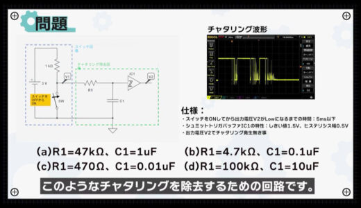
Now, suddenly, here is the problem.
Which of the following combinations of circuit constants is suitable for eliminating this chattering?
In addition, the specifications described herein shall be satisfied.
Incidentally, an RC circuit for removing chattering can be designed with a time constant (R x C) on the order of a fraction to 1/10 of the chattering to remove chattering comparatively well.
*Press the answer button to get the answer.
The time constants for each condition are shown in the figure below, with condition (b) being closest to the approximate range.
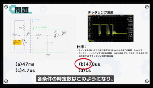
In addition, actual simulation under the conditions (a)-(d) confirms that only (b) satisfies the specification.
How to reproduce measured voltage waveforms in LTspice
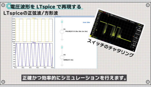
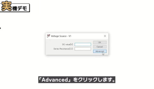
We will show you the results of the simulation later, but first we will explain how to import the actual chattering waveforms into LTspice as a preparation.
LTspice provides voltage sources such as sine and square waves, but complex waveforms such as switch chatter are difficult to create, so it is more accurate and efficient to import actual measured waveforms for simulation.
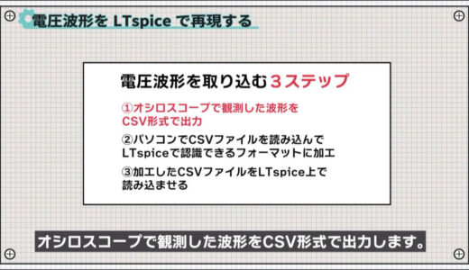
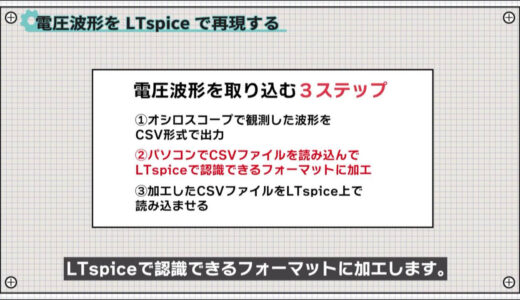
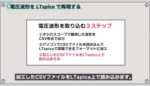
There are a total of three steps for capturing voltage waveforms.
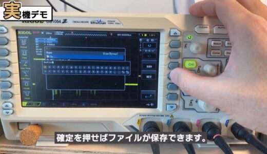
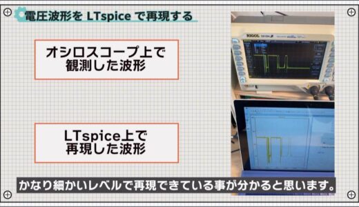
- Output waveforms observed by oscilloscope in CSV format
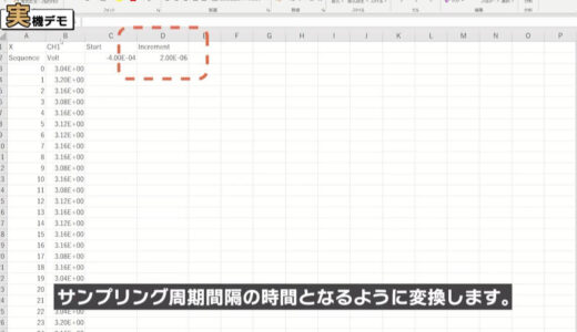
- Read CSV files on a PC and process them into a format that can be recognized by LTspice
- Read the processed CSV file on LTspice

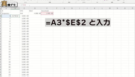
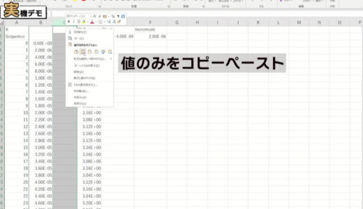
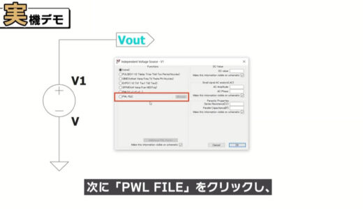
Next, we will take a closer look at step (2), which is to read the CSV file on the computer and process it into a format that can be recognized by LTspice.


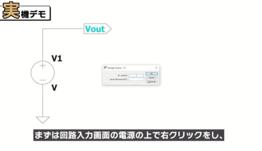
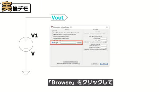
Finally, we will look at the procedure for reading the processed CSV file into LTspice as step (3).
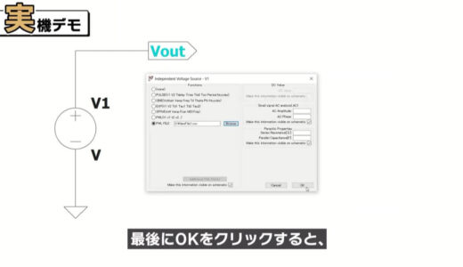
If you compare the waveform observed on the oscilloscope with the waveform reproduced on LTspice, you will see that it can be reproduced at a very fine level of detail.
How to remove chatter
We will now describe the circuit to eliminate chattering.
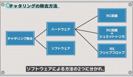
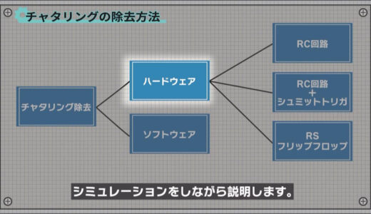
There are two main methods of chatter removal: hardware and software, and three additional methods within hardware.
In this section, we will focus only on hardware and explain it with simulations.
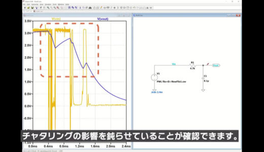
First of all, the most basic RC circuit is in the form of a so-called low-pass filter made only of R and C, as shown here.
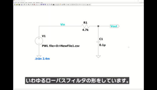
When V1 is High level, C1 is charged via R1, and when V1 is Low level, C1 is discharged from C1 via R1.
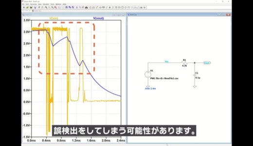
Applying the simulation, it can be seen that Vout varies slowly according to the time constant of R1 × C1, thus blunting the effects of chattering.
However, since Vout fluctuates slowly and chattering cannot be completely eliminated, for example, if the destination of Vout is connected to a general-purpose I/O port of the CPU, a false detection may occur if the voltage fluctuates near the threshold at which the CPU detects High/Low.
Therefore, to compensate for the weakness of the RC circuit, a Schmitt trigger buffer was added, as shown in the following image.
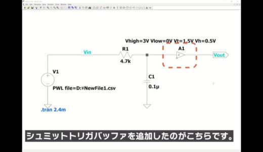
A1 is a buffer with hysteresis characteristics: the threshold of the input voltage level at which the output switches from Low to High is different from the threshold of the input voltage level at which it switches from High to Low.
In this example, the output switches from High to Low when the input voltage of A1 falls below 1.0 V and from Low to High when it rises above 2.0 V.
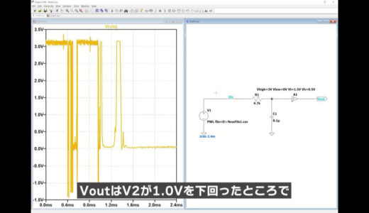
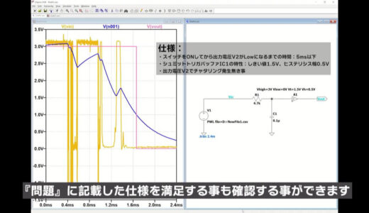
If you run the simulation, you will see that Vout completely switches from High to Low when V2 falls below 1.0V, although there are some voltage fluctuations in the V2 section.
 |
 |
Chattering removal using RS flip-flops
We can also confirm that this circuit satisfies the specifications described in the “Problem” section.
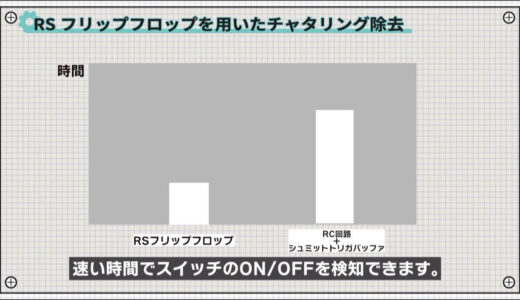
There are other methods of removing chattering using RS flip-flops, so I will only introduce them here.
Using this method, a switch ON/OFF can be detected in a faster time than an RC circuit + Schmitt trigger buffer.
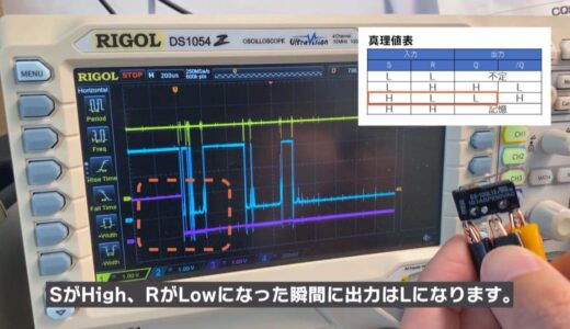
RS flip-flops are logic ICs with a truth table as shown in the figure below , and one feature of RS flip-flops is that they have a state called memory.
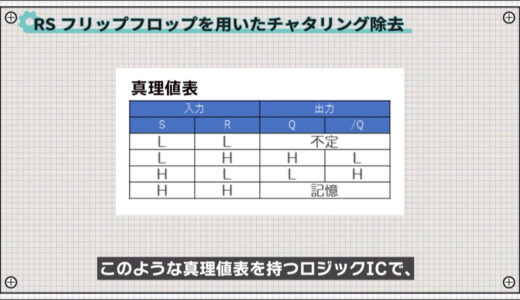
For example, when the switch is turned from OFF to ON, the output goes Low the moment S goes High and R goes Low.
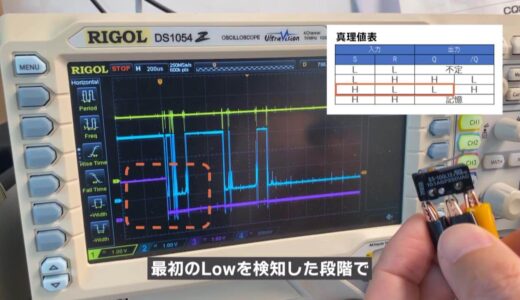
After that, R repeats High/Low due to chattering, where it remembers the previous value, so it remains Low.

As a result, the output will be able to detect the switching at the first Low detected without chattering.
These are three ways to remove chatter.
summary
In this issue, under the theme “Be careful of chattering when switching on and off,” we have talked about the reasons why chattering occurs and the circuits to prevent it.
Although the switch appears to be a simple component, it should be handled with care.
Also, if you want to reduce the circuit size, you should consider software measures.
This site also provides other videos and articles to help beginners learn electronics construction systematically from zero, including explanations of the minimum knowledge and tools they need to acquire.
\電子工作歴9年の私のイチ押し!ELEGOOの電子工作キット/