YouTube
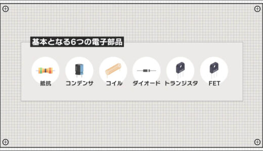
This section describes the principles and structures of the six very basic electronic components.
There was an error in some parts of the video.
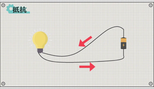
9:56 Correctly, the direction of the plus and minus of the battery is the same in (a) and (b).
Please note that the direction of “+” and “-” in (b) was reversed.
Principles and Structures of Very Basic Electronic Components


This article describes the principles and structure of electronic components.
If you read this article to the end, you will learn more about electronic components and enjoy electronic construction more.
resistance
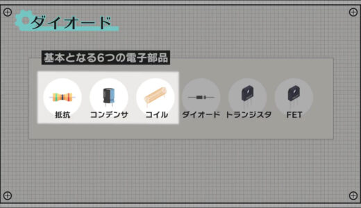
We will first explain the principle and structure, focusing on the six very basic electronic components.
- Components that control and process electricity
- Components that measure the world
- Parts that work
- Components that perform a specific operation or process
- Energy Source Components
- Components for electronic equipment
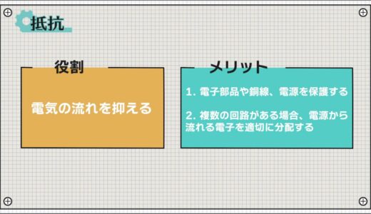
First, we will discuss resistors, the most basic of all electronic components.

The main role of resistance is to “restrain the flow of electricity,” and by restricting the flow, the advantages listed here are created.
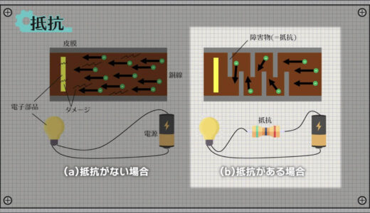
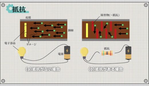
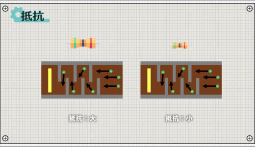
The following figure illustrates the role of resistance in the model.

Within the model, resistance can be represented by obstacles that interfere with the flow of electrons.
(A) represents the case where there is no resistance, and it can be seen that without resistance, a large amount of electrons flow from the power supply, the source of the electrons.
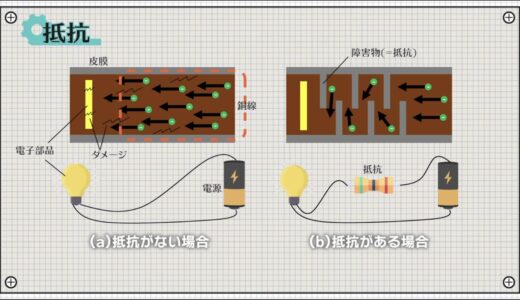
This can result in damage to connected electronic components and wiring.
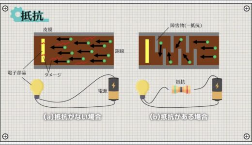
The power supply also cannot send an infinitely large number of electrons, so there is a risk of damaging the power supply due to excessive flow.
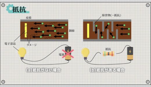
The resistance used there is the obstacle, resistance, as shown in (b).
Placing obstructions can interrupt the flow of electrons, allowing them to flow a little at a time.
As a result, electronic components, copper wires, and power supplies can be protected.
Also, there is a limit to the amount of electrons that can be supplied by the power supply.
Therefore, if a circuit has multiple routes, electrons must be properly distributed to each route.
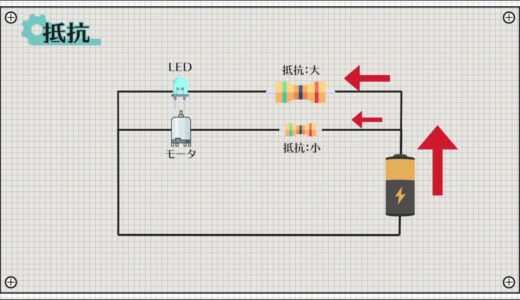
In this case, resistors can be used to adjust the amount of electrons and distribute them easily.
The size of the resistance value corresponds to the size of the obstacle.
The next image below shows a real photograph of a partially opened resistor package and an image of its cross section.
Simple in construction, the body is made of ceramic and surrounded by a carbon film.
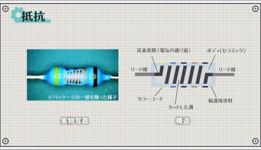
Because ceramic is an insulator, electricity does not flow through it; instead, it flows through the carbon film on its surface.
Carbon film has a tendency to conduct electricity, although not as much as metals.
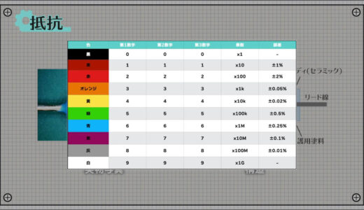
On the outside of it is a protective coating and further outside of that is a colorful line called a color code.
Each color code is assigned a meaning, and you can read the magnitude of its resistance just by looking at the code below.
capacitor
Next is the capacitor.
Capacitors are the second most commonly used electronic component after resistors.

It is mainly used “where you want to reduce voltage fluctuations.
The role of a capacitor is to “temporarily store electricity like a bucket.
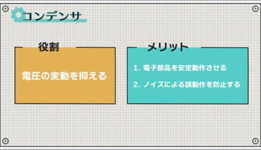
Storing electricity can be used to
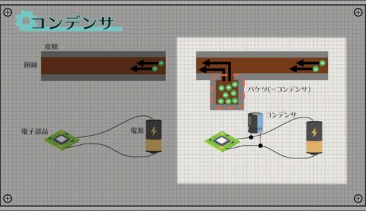
The figure below is an imaginary drawing of the role of a capacitor.
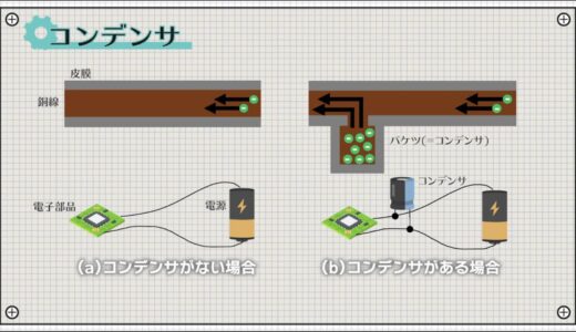
The amount of current required to operate electronic components such as integrated circuits (ICs) is not always constant, but can fluctuate depending on their condition.
At that time, if you try to supply them from a distant power source, the supply of electrons may not arrive in time, resulting in malfunctioning.
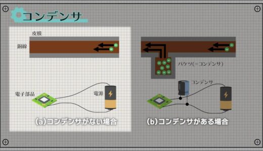
At such times, if there is a capacitor nearby, as shown in this figure, the electrons temporarily stored in it will flow out and replenish the missing parts in the electronic components.
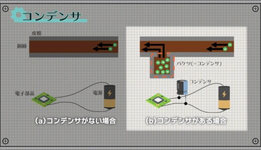
This allows for stable operation of electronic components.
In addition, electronic circuits are exposed to various types of noise, such as static electricity and electromagnetic waves.
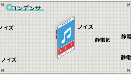
If noise gets on the circuit, the voltage will fluctuate rapidly, and there is a risk of reading incorrect voltage values or destroying electronic components.
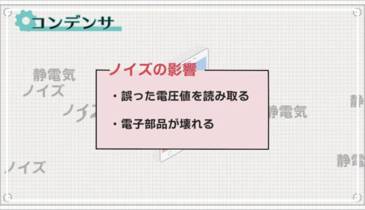
In such cases, a capacitor can reduce the amount of voltage fluctuation by storing a temporary increase in electrons like a bucket.
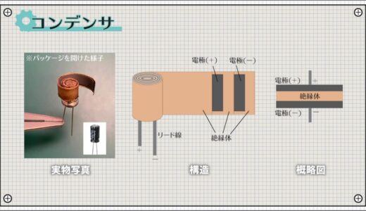
The following figure shows a picture of an open capacitor package and illustrates the structure.
As shown here, the capacitor has a layer of insulator between the positive and negative electrodes, each wrapped around in a thin film.
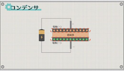
The following figure shows the voltage applied to the capacitor.
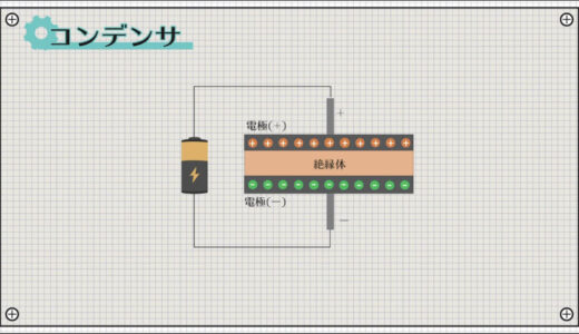
The capacitor has a positive and a negative electrode placed between insulators.
This insulator does not conduct electricity, but because it is made very thin, the positive on the positive electrode side and the negative on the negative electrode side are attracted to and held by each other.
coil
Coils, introduced next, are rarely seen in everyday life, but they are a behind-the-scenes force among electronic components.

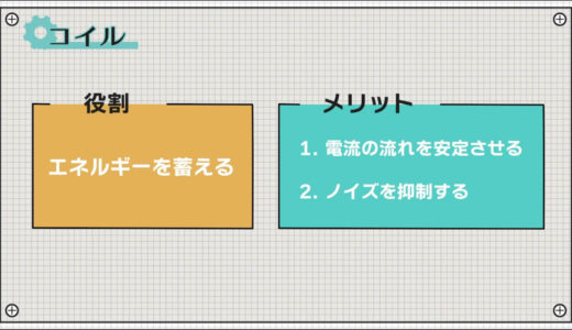
The role of the coil is similar to that of a “water wheel”.
When coils are applied to electrical circuits, the following can be achieved
The waterwheel is slow to start turning, but once it starts turning, it does not stop immediately even if the water supply is stopped, but keeps turning for a while.
From a different perspective, it can be said that the waterwheel keeps turning by storing energy and slowly releasing it.
The following figure is an example of this property applied to an electric circuit.
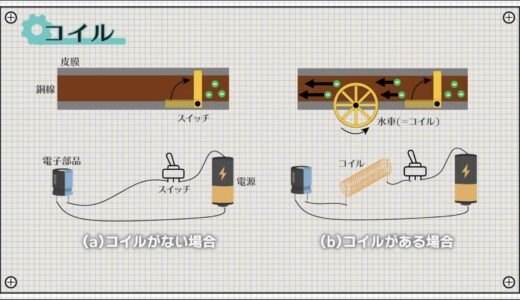
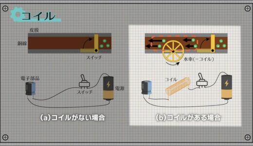
As shown in the figure below, if there is no coil, turning off the switch interrupts the flow of electrons, at which point the supply of electrons to the electronic components stops.
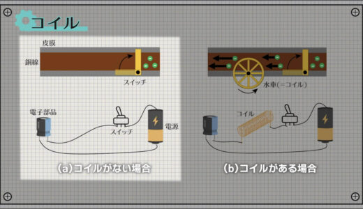
On the other hand, if there is a coil, it will continue to supply electrons even after the switch is turned off, and will continue to do so for some time, although the supply will gradually decrease.
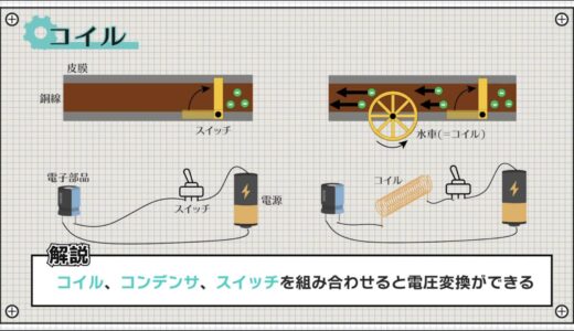
The combination of this inductor and capacitor can achieve a voltage conversion similar to a DCDC converter.
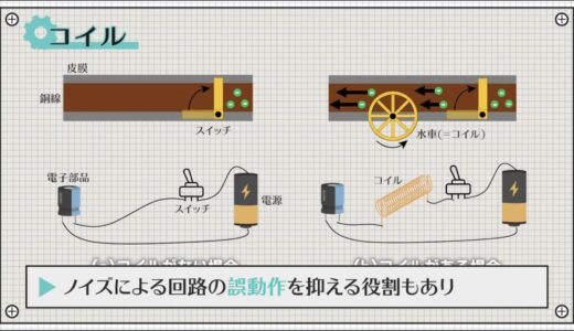
Also, the fact that the waterwheel starts turning slowly means that the flow of electrons can be suppressed even if the flow increases rapidly in a short period of time due to noise.
Therefore, coils, like capacitors, also play a role in suppressing circuit malfunctions caused by noise.
Below is a schematic diagram of the actual coil and its construction.
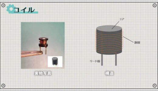
The construction is very simple: simply wind copper wire around a magnet called a core, and the coil is complete.
The three components described so far are components that process the form of electricity by consuming energy received from outside.
On the other hand, the three components introduced here are components that control electricity based on the energy received.
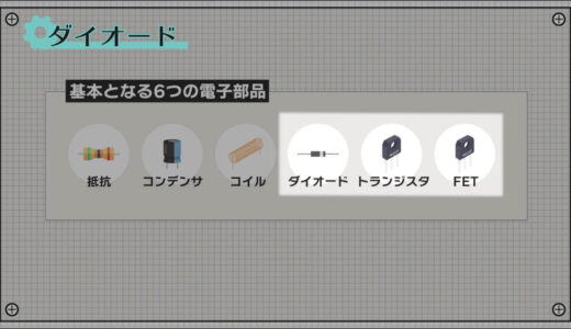
diode
Semiconductors are mainly used for components that control electricity, and we will start with the most basic application of semiconductors: diodes.

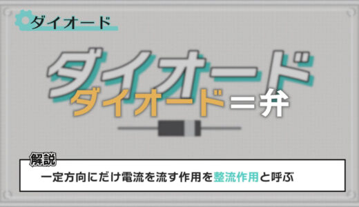
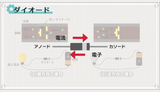
The role of the diode is to allow flow in only one direction, like a “valve”.
This is called rectifying action, meaning regulating the flow.
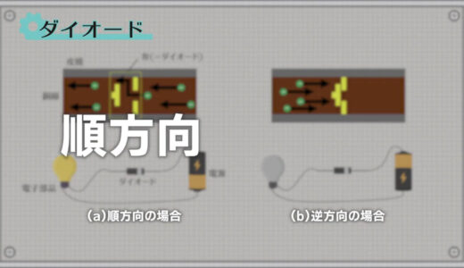
As shown in the figure below, in case (A), the flow of electrons pushes the lid of the valve, allowing electrons to pass through.
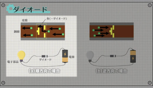
This direction is called the forward direction because current will flow through the diode.
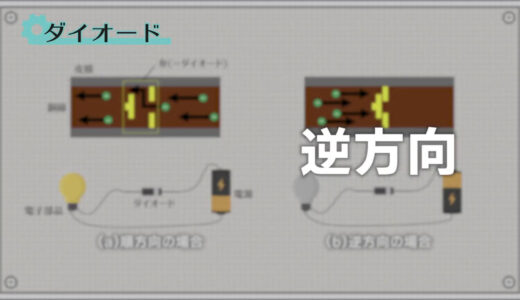
On the other hand, if electrons flow in direction (B), the valve lid will be in the closing direction, so electrons cannot pass through the diode.
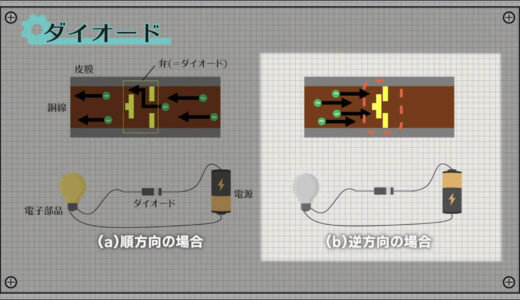
This is called the reverse direction.
As a result, electrons can only flow in the forward direction.
The terminals of the diode are named anode and cathode, with electrons flowing from the cathode to the anode and current flowing from the anode to the cathode.
The following figure depicts a photograph of the diode and an image of its structure.
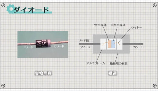
When the contents of a diode are magnified, they are in the form of a P-type semiconductor and an N-type semiconductor attached to each other.
The semiconductor chip rests on an aluminum frame, and the aluminum frame is connected by thin wires made of gold or other material.
The following image then illustrates how the diode rectifies.
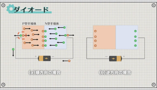
P-type semiconductors have more holes and N-type semiconductors have more electrons.
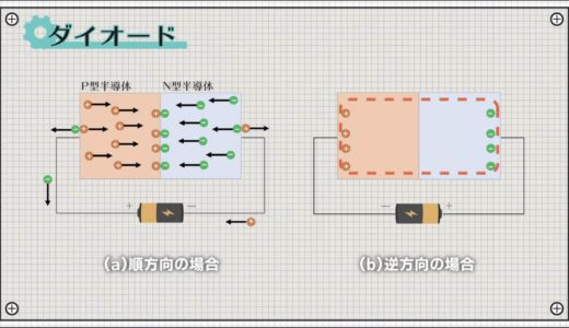
When power is applied in the direction of (A), the holes are repelled from the positive side of the power supply and the electrons are repelled from the negative side of the power supply, so the holes and electrons move toward the direction of the interface where they are joined respectively.
A hole represents a lack of electrons, so when a hole and an electron meet, they combine with each other to become electrically neutral and disappear.
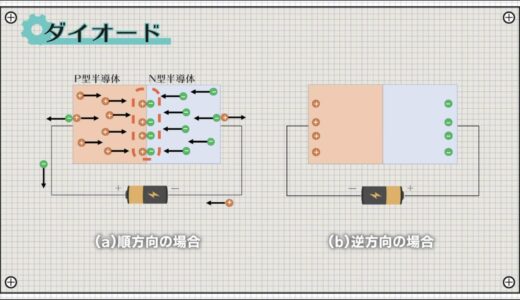
The new N-type semiconductor is injected with electrons, and the P-type semiconductor is drained of electrons and injected with holes instead.
And since the power supply continues to supply holes and electrons, these holes and electrons are combined and lost one after another.
On the other hand, when the power supply is connected in the opposite direction as in (B), electrons move to the positive side of the power supply and holes move to the negative side.
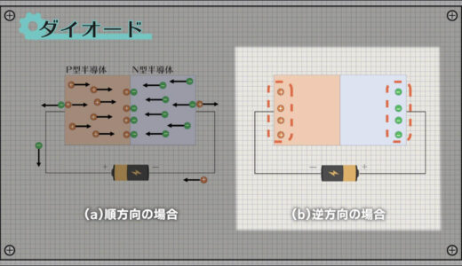
As a result, the electrons and holes are separated and do not meet each other and are not coupled.
At this time, there are no electrons or holes near the interface between the P-type and N-type semiconductors, so the area is an area where no electricity flows.
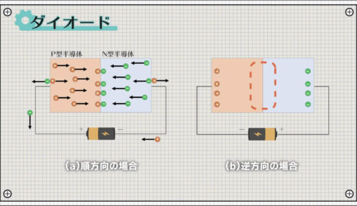
Thus, if the power supply is connected in direction (B), it will not be possible to create a continuous flow of electrons and holes, and no current will flow.
electrical transistor
Next, we introduce the transistor, which is an important semiconductor component along with the diode.
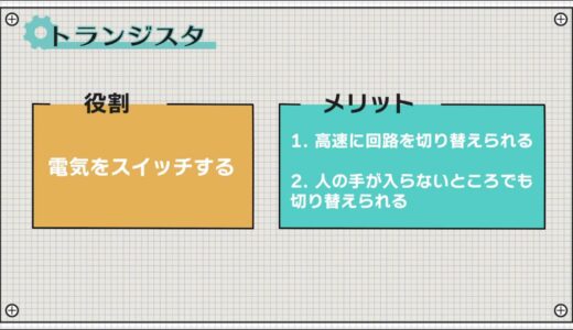
The role of the transistor is to “switch electricity.
Unlike physical switches that are turned on and off with a flick of the hand, electrical control has the advantage of switching circuits at high speeds and inaccessible to the human hand.
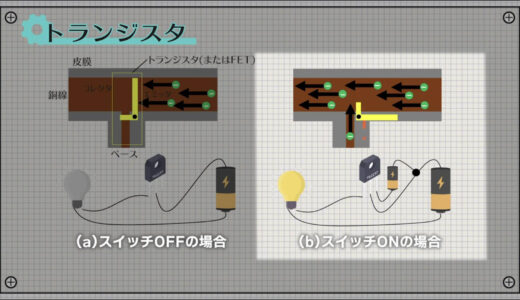
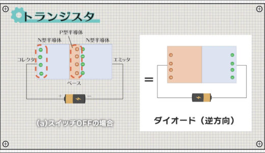
The following image illustrates the role of a transistor.
Transistors are represented by the yellow dotted line in the figure.
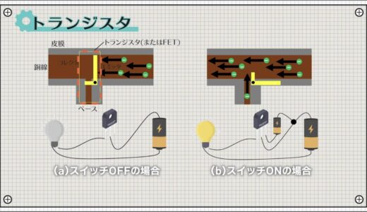
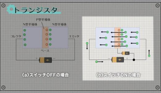
The base terminal is responsible for switching the transistor on and off, and if no electrons are flowing, as shown in (a) in the following image, they are blocked by a large L-shaped wall between the collector and emitter terminals and cannot flow.
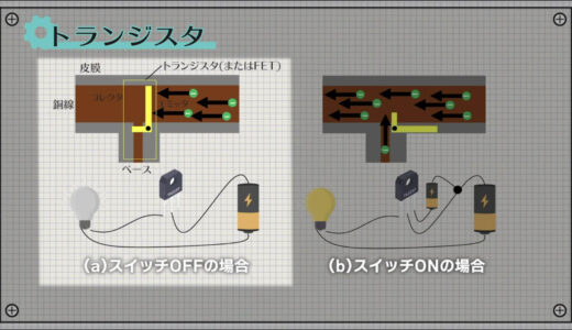
On the other hand, when electrons are injected into the base as in (b), the wall collapses and an opening occurs between the collector and emitter, allowing current to flow.
The structure of the transistor is shown in the figure below, with three legs protruding from the component.
The legs are called “emitter, collector, and base,” respectively. The emitter and collector are connected to an N-type semiconductor and the base to a P-type semiconductor.
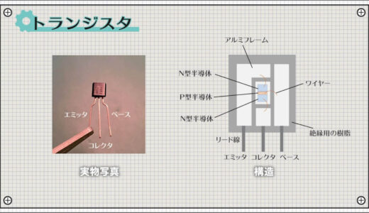
Also like diodes, transistors have their respective leads connected to aluminum frames, and aluminum wheels are connected to semiconductor chips through wires.
The following image then illustrates the principle of transistor operation.
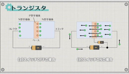
In image (a) below, voltage is applied only between the collector and emitter.
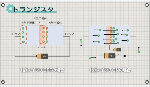
At this time, the electrons in the connector move to the left side of the figure and those in the base move to the right side of the figure, resulting in the diode applying voltage in the opposite direction.
In this state, holes and electrons do not meet and the flow is stagnant, so no current flows.
Now let us apply a voltage between the base and emitter as in (B).
At this time, the holes in the base and the electrons in the emitter go in each other’s direction, and the holes and electrons meet and disappear.
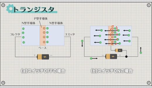
Because the base is very narrow, the voltage applied between the base and the emitter causes the electrons to jump over the base with great force and electricity flows.
FET
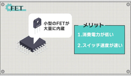
The last component, FET, is a relative of the transistor.
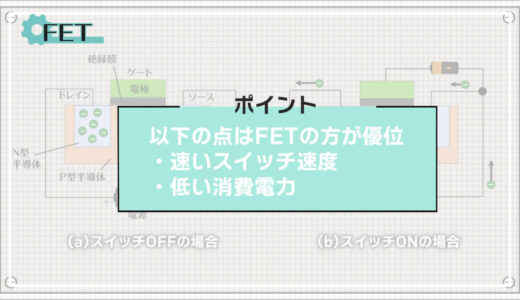
CPUs are often made with FETs because FETs switch faster and consume more power than transistors.
The role of the FET, like the transistor, is to switch electricity.
The following image shows the structure of a FET, which, like a transistor, has three legs coming out of the component, called “gate, drain, and source,” respectively.
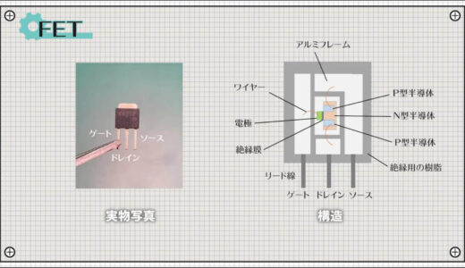
The gate is connected to the electrode and the drain-source to the P-type semiconductor.
The P-type semiconductor is surrounded by an N-type semiconductor, and a film made of insulator is stretched between the N-type semiconductor and the gate electrode.
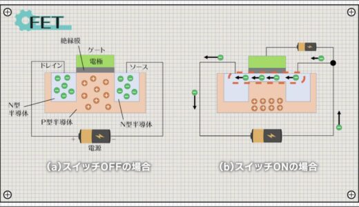
In (a), no voltage is applied to the gate, only between the drain and the source.
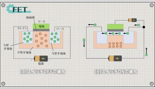
Looking at the area enclosed by the dotted line in the figure below, the N-type, P-type, and N-type semiconductors are lined up from the drain side, so no electricity flows at this time, just as when a transistor is switched off.
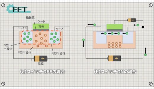
As shown in (b), the situation changes slightly when a voltage is applied between the gate and the source.
Since a + voltage is applied to the gate, the holes in the P-type semiconductor will move away from the gate if they go near the gate.
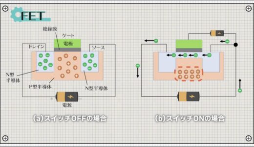
Many holes are present in P-type semiconductors, but there are also a few electrons.
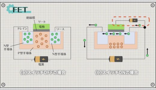
This creates a route for electrons between the drain and the source, allowing electricity to flow.
Like a transistor, an FET creates a flow of electricity by applying a voltage to a semiconductor in the middle.
However, FETs have advantages such as faster speed from the application of voltage to the formation of electrical current and lower resistance of the electrical route.
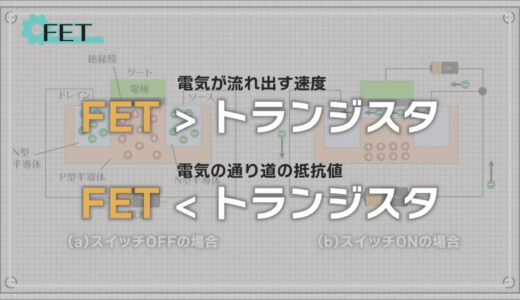
Therefore, FETs are preferred for applications that require fast switching speeds and low power consumption.
summary
The above has been a detailed explanation of the principles and structure of the six most basic electronic components.
This site also provides other videos and articles to help beginners learn electronics construction systematically from zero, including explanations of the minimum knowledge and tools they need to acquire.
\電子工作歴9年の私のイチ押し!ELEGOOの電子工作キット/