
YouTube
0:00 Opening
0:14 Usage (1) Current Suppression
0:55 Usage (2) Separate voltage
1:56 Usage (3) Stabilizing voltage
3:12 Summary
The “very” basic use of resistance


In this issue, we will introduce three very basic uses of resistors, which are key components in electronic construction, with examples under the title of “Super” Basic Uses of Resistors.
The basic use of resistors will be explained in detail, so even beginners in electronics should be able to understand it.
Please see the end of this section, as understanding resistors will give you a foothold to use many electronic components.
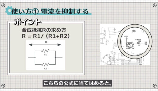
How to use resistance (1)
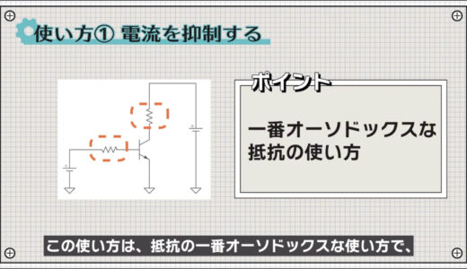
The first is the use of current suppression.
Since the maximum current that can flow through power supplies and electronic components is fixed, resistors are used to limit the current so that it does not exceed the maximum current.
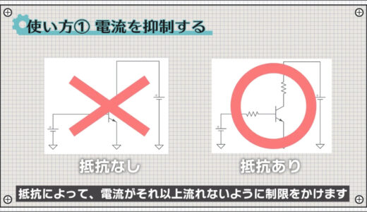
This is the most orthodox use of resistance and can be seen everywhere.
For example, in Arduino, it is used in several places to limit the current flowing to LEDs.
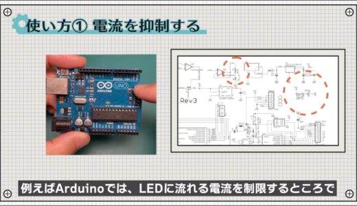
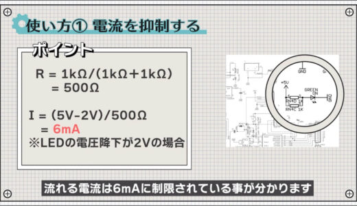
In this part, say, two 1kΩ resistors and an LED are connected to 5V.
Then, since the overall resistance is 500Ω, Ohm’s law indicates that the flowing current is limited to 6mA.
 |
 |
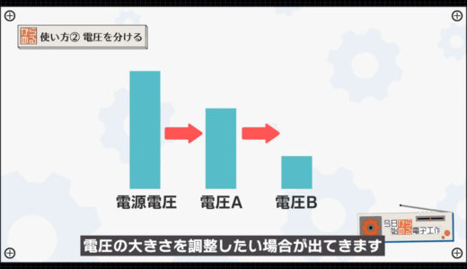
Resistance usage (2)
The next use is to divide the voltage, which is also technically called voltage divider.
When you are working on a circuit, you may want to adjust the magnitude of the voltage.
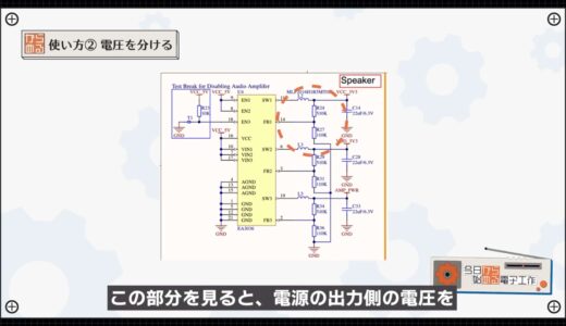
For example, the following M5Stack circuit is a buck converter circuit that converts a USB 5V voltage to 3.3V using a switching method.
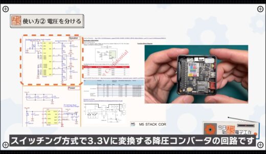
The following section shows that the voltage on the output side of the power supply is divided by 510k and 110kΩ resistors and connected to the feedback terminal.
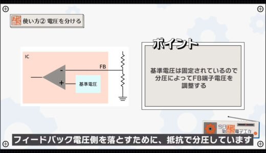
Inside the IC, the switching is turned on and off by comparing a certain reference voltage with a feedback voltage.
However, since a very large reference voltage cannot be made, the voltage is divided by a resistor to drop the feedback voltage side.
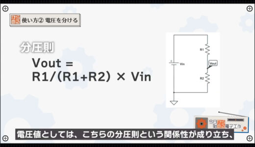
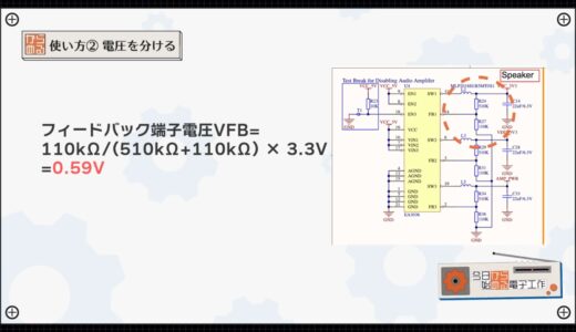
As for the voltage value, the voltage divider rule relationship shown in the figure below holds, and the feedback terminal voltage is Vfb = 110k/(510k+110k) x 3.3V = 0.59V.
 |
 |
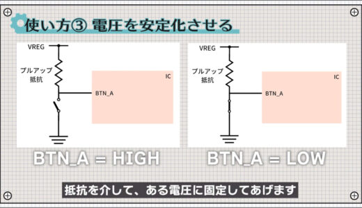
Resistance usage (iii)
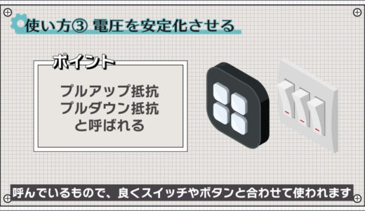
The next use is to stabilize the voltage.
These are what we call pull-up and pull-down resistors, and are often used in conjunction with switches, buttons, etc.
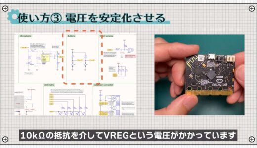
For example, the button on the microbit shown below has the voltage VREG applied via a 10kΩ resistor.
If the configuration were only switches, when the button is on, the voltage would be stable because it is connected to GND, but when it is off, nothing would be connected to the GND.
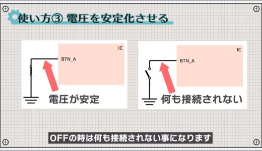
At this time, from an electrical point of view, it is equivalent to having an infinitely large resistance connected, and if even a small amount of current flows through it due to noise, etc., the voltage will fluctuate and create an unstable state.
This condition is commonly referred to as a “floating” condition.
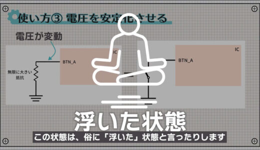
To avoid creating a floating state, let’s fix it at a certain voltage via a resistor as shown in the circuit below.
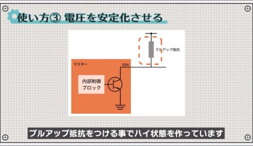
It is also known that a pull-up resistor is required on the output line of I2C, one of the major communication methods, as shown in the figure below.

This is because the output pins of the IC are not connected to the power supply and can only create a low state.
When not low, the transistor is turned off, so a pull-up resistor is added to create a high state.
Finally, I will summarize the three uses of resistance once again.
- suppress current
- separate the voltages
- Stabilize voltage
summary
In this issue, we introduced three uses of resistors, one of the main components of electronic circuits.
What we have discussed here is only the very basic use, and there are many more ways to use the resistance, which I hope to introduce again in other videos and articles.
On this site, we post videos and articles that allow you to systematically learn electronics construction from scratch, including explanations of the minimum knowledge and tools you need to acquire.
\電子工作歴9年の私のイチ押し!ELEGOOの電子工作キット/