
0:00 Opening
0:33 What is common impedance?
1:42 Example: Wiring without considering common impedance
5:58 Improvement method considering common impedance
7:57 Demonstration of actual equipment
9:07 one point
9:59 Summary.
Beware of common impedances that interfere with operation.
I’ve connected the wires for now, but it’s not working right.


This time, I would like to talk about the theme of “beware of common impedance that interferes with operation” for those who think that wiring should be connected anyway.
This article will explain in detail, with pictures, what common impedance is in the first place, and the effects of common impedance using actual equipment.
Even if you think that wiring just needs to be connected for now, by the time you finish reading this article, you should be able to create a circuit that takes common impedance into account!
What is common impedance?
To begin with, a brief explanation of the meaning of common impedance is in order.
Since it may not be clear from words alone, I will explain it with a circuit diagram.
When current flows in Circuit A and Circuit B, respectively, the area enclosed by the red square below is a common impedance because current flows in common.

When current flows between Circuit A and Circuit B as shown in the board pattern below, the orange line is the common impedance because the board pattern also has a resistance value.

The presence of a common impedance on the circuit causes the following two problems
- Currents from multiple circuits are concentrated at that point, resulting in a larger current value flowing and a larger voltage drop
- Voltage drop increases or decreases depending on the magnitude of current flowing in other circuits, making it susceptible to other circuits
Let’s take one example and see how this common impedance actually affects the circuit.
Effect of common impedance on circuits
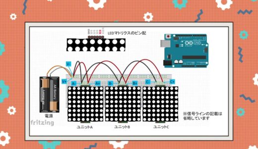
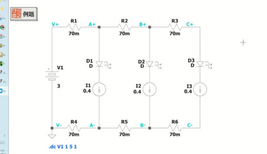
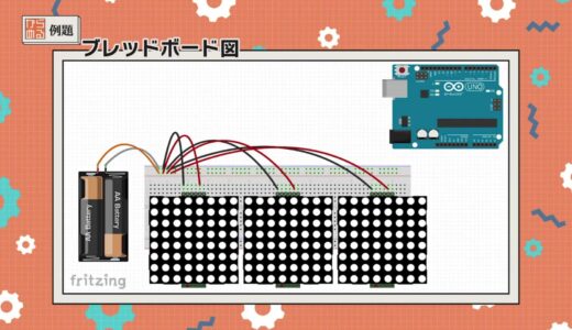
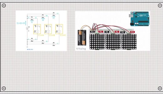
This time, I set up a circuit using three components called LED matrix to create a prototype of a tabletop display.
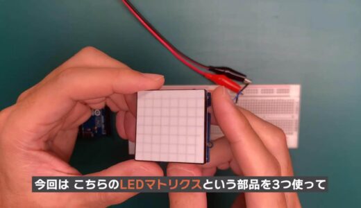
The breadboard diagram of the assembled circuit is shown below.
 Now here is the question.
(A) 2.80V (B) 3.02V (C) 3.14V (D) 3.49V
- Jumper wire: 70 mΩ resistance per wire
- LED matrix: current consumption 400mA per unit
- Resistance value should be 0Ω except for the red/black jumper wire
Because of the resistive component, a common impedance is created depending on the wiring method.
Referring to the breadboard diagram, let us consider what the equivalent circuit would look like in this case.
Think about it for a moment before looking at the answer.
interpoint (interword separation)
interpoint (interword separation)
interpoint (interword separation)
Now for the solution.
*Press the answer tab below to get the answer.
The following is a step-by-step explanation.
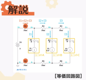
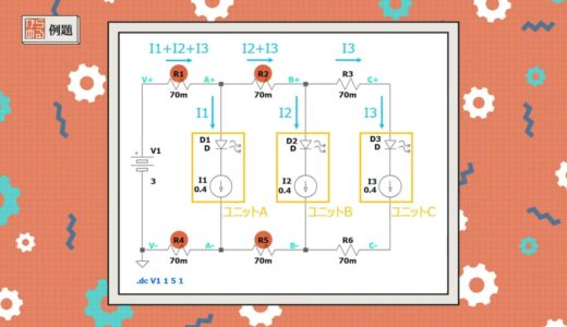
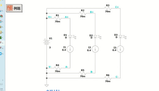
First, the following figure shows the equivalent circuit for this circuit using resistors and current sources.
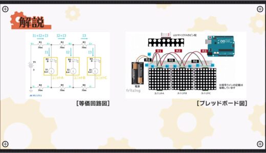
With this type of wiring, the sum of the currents in units A, B, and C, I1+I2+I3, flows through jumper wire R1, which is closest to the power supply.
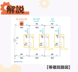
The same is also true for R4, which is in the path of the current return.
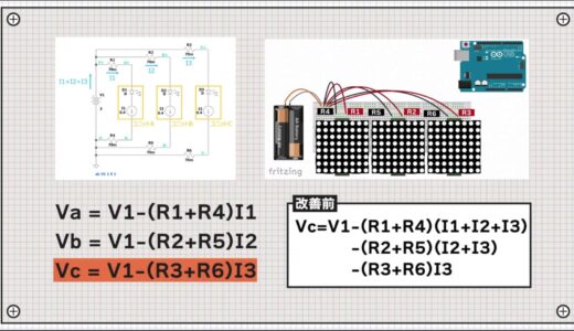
The resulting voltage at both ends Va applied to unit A, here the potential difference between A+ and A-, is the voltage described in the following equation.
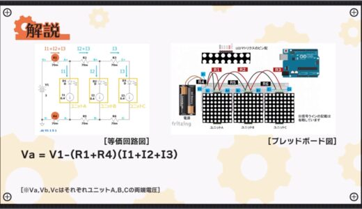
Similarly, the voltage at both ends of unit B and unit C in the latter stage can be expressed by the following equation.
Vc=Vb-(R3+R6)I3
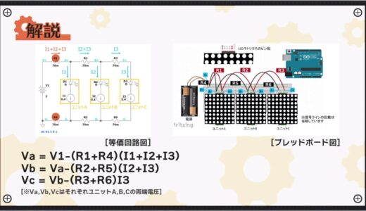
Expanding these equations, the voltage Vc at both ends of unit C, which is furthest from the power supply, is expressed by the following equation
-(R2+R5)(I2+I3)
-(R3+R6)I3
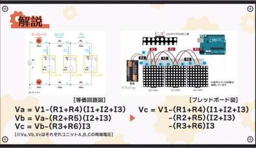
The second, third, and fourth terms (orange line in the figure below) all take negative values, so many factors are subtracted from the main source voltage, V1.

As a result, it is clear that the voltage values have become smaller.
Wiring without consideration of common impedance
Next, let’s use a circuit simulation called Ltspice to see how much the voltage at both ends of unit C actually drops.
I would like to simulate the above circuit, this time using the mode DCsweep.
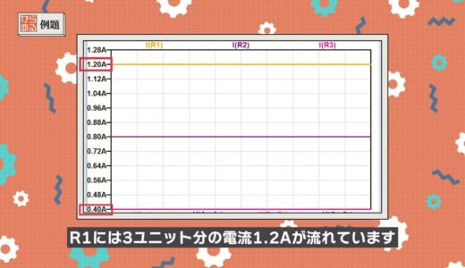
First, monitor the voltage and current in each section.
Looking at the current in each section in the following image, only 0.4A, the current for one unit, flows in R3 (pink line), but 1.2A, the current for three units, flows in R1 (orange line).
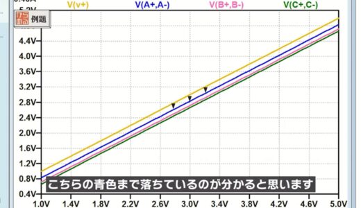
Next, the power supply voltage is swept from 1.0V to 5.0V for simulation as shown in the following figure.
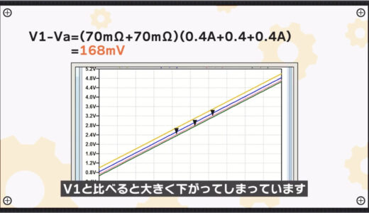
The orange line at the top is V1, but you can see that a large voltage drop occurs from V1 due to the concentrated current flow of the three units, and the voltage drops to blue.
Calculating from the previous formula for Va, the voltage drop V1-Va is 168mV.
=168mV
Although the amount of voltage drop from the previous stage decreases as one moves to the latter stage, the voltage at both ends of unit C in the last stage has dropped significantly compared to V1.
Calculating here too, the voltage drop from V1, V1-Vc, is 336mV.
+(70mΩ+70mΩ)(0.4A+0.4A)
+(70mΩ+70mΩ)0.4A
=336mV
This means that the voltage at both ends of unit C will be 336mV lower than the supply voltage.
In this state, the power supply voltage V1 = 2.8V + 0.336 = 3.136V or more is required to ensure the guaranteed operation voltage of 2.8V for the LED matrix.
Therefore, (C), 3.14V, is the correct answer.
When wiring is done as shown in the following figure, we found that a potential difference of more than 0.3V is generated between the power supply voltage and the end units.
The very cause of this difference is the common impedance I described at the beginning.
In this example, R1 and R4, R2 and R5 are such examples.
So next I would like to make an improved wiring considering the common impedance.
The assumption is that the cables and components used are the same.
Improvement method considering common impedance
To improve the common impedance, we wired as shown in the following figure.
The only difference from the previous wiring is that the red and black wires have been reconnected to the lines of the indicating section.
The breadboard diagram is shown below.
An equivalent circuit of this wiring is shown below.
The power supply for each unit is connected directly to the power supply via jumper wires close to the power supply, so each resistor will hang in parallel independently of each other from the power supply.
As a result, we were able to create a circuit with no common impedance.
As is clear from this circuit diagram, the voltage at both ends of each unit is expressed as follows equation
Vb = V1-(R2+R5)I2
Vc = V1-(R3+R6)I3
Comparing the expression for Vc after wiring improvement with that before improvement, it is clear that there is less negative term on the right side.
Again, we can use LTspice to see the difference in voltage effects.
The current and voltage of each section will be plotted.
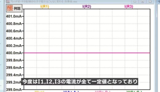
If we look at the currents in the following figure, we now see that the currents I1, I2, and I3 are all constant values.
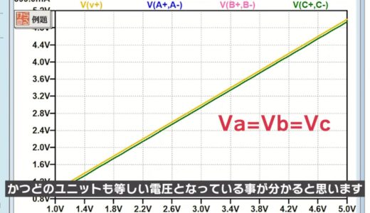
Next, looking at the voltages in the following figure, we see that the voltage drop from the power supply voltage V1 is as small as several 10 mV, and furthermore, all units have the same voltage.
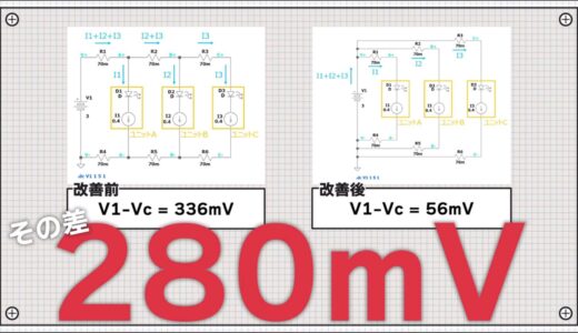
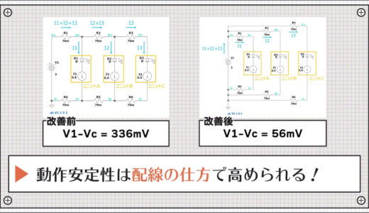
The actual calculation of the equation shows that the voltage drop V1-Vc is 56mV.
Compared to 336mV before the wiring improvement, the voltage drop has been reduced by 280mV.
Although we only changed the wiring on the breadboard, we were able to greatly reduce the amount of voltage drop.
Furthermore, as a result, it is now possible to choose a lower supply voltage.
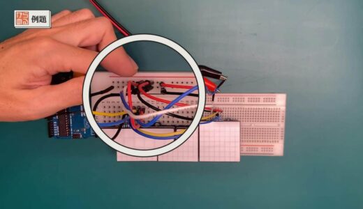
Finally, let’s use an actual device to actually check the effect of common impedance.
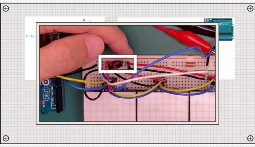
Demonstration of actual equipment
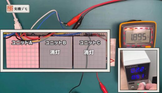
In the actual demonstration, the wiring is intentionally made to have a common impedance, as in the first circuit of the example.
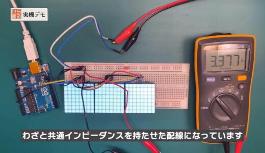
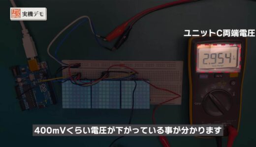
If we measure the voltage at both ends of the power supply voltage and at both ends of unit C in this state, we find that the voltage at the point of unit C is about 400mV lower as shown in the figure below.
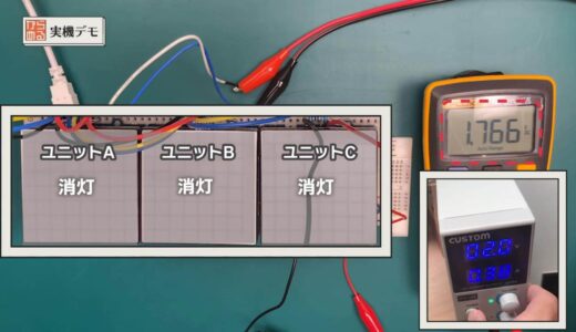
If a sufficiently high supply voltage is available, this voltage difference is rarely a problem.
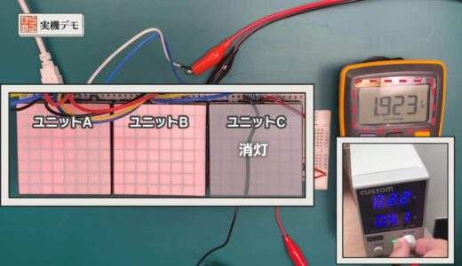
However, as the power supply voltage is gradually lowered, the circuit operation gradually becomes unstable from unit C.
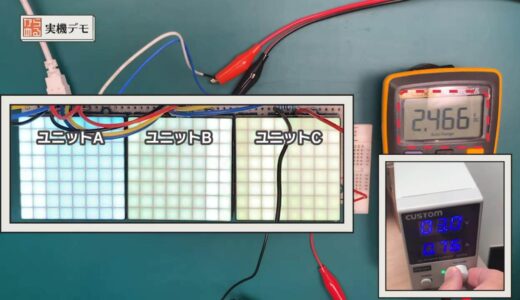
If you want multiple units to have similar brightness and identical operation, it is important to keep the power supply voltages as close together as possible.
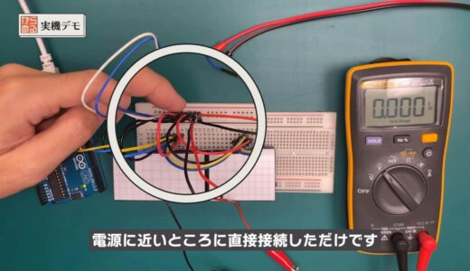
To keep the supply voltage aligned, the common impedance will be improved to be smaller.
As in the previous example, simply rewire the power supply ground and connect it directly near the power supply as shown in the figure below.
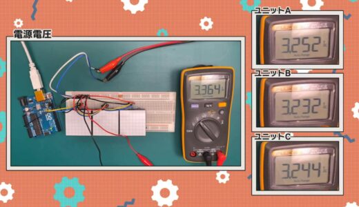
As shown in the figure below, the potential difference from the supply voltage was quite small, and the voltages of units A, B, and C could be kept at the same level.
That is all for the explanation.
Although we have used breadboards for this explanation, common impedances actually occur everywhere, including cables and board patterns.
advice of a point (advice that may be helpful to some people)
One last point of advice.
Using LTspice circuit simulation, as we have done this time, circuit behavior can be quickly verified on a PC.
This not only improves the efficiency of development, but also allows for safe examination, making LTspice an indispensable tool for electronic work.
We also encourage anyone who is “unsure of how to use it or what it is for” to sign up for CQ Publishing’s newsletter.
>>Click here for a list of CQ Publishing’s e-newsletters.
They examine and distribute stories like this one every week, so you can become familiar with simulations and circuits.
summary
In this issue, we have talked about “beware of common impedances that interfere with operation” for those who think that wiring should be connected anyway.
How to capture the invisible is the key to reducing common impedance.
\電子工作歴9年の私のイチ押し!ELEGOOの電子工作キット/