
YouTube
0:00 Opening
0:56 What is a breadboard?
2:24 How to use a breadboard
3:20 Breadboard Structure
4:24 Actually build the circuit
5:20 One Point Advice
5:36 Summary.
Basic Breadboard Usage


In this article, we will go into detail about breadboards for those who are unfamiliar with them.
Learning how to use a breadboard will make electronic construction more fun by allowing you to build circuits easily and quickly.
When you finish reading this article, You will have enough knowledge to build a breadboard right now.
Let us begin by explaining what a breadboard is.
What is a breadboard?
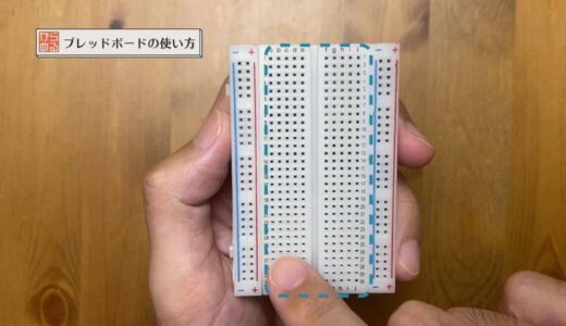
The breadboard has many holes, as shown in the figure below, so that components and cables can be inserted in any desired position.

When building circuits in electronic construction, you have two choices: either a flat board called a universal board or a breadboard.


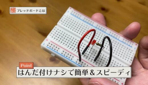
What are the advantages of using a breadboard? The advantage of using a breadboard is that soldering is not required, and circuits can be built quickly and easily.
Conversely, a disadvantage is that it is less reliable.
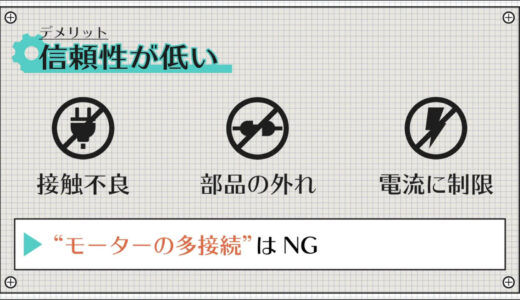
- Breadboards have only pins sandwiched inside, so they are prone to contact failures and parts coming off.
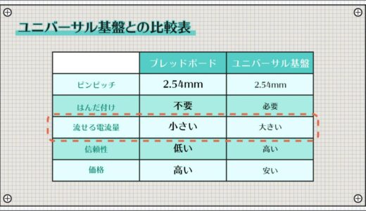
- There is a limit to the current that can flow through the pins, making them unsuitable for high-current applications.
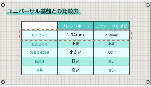
To make things a little clearer, here is a summary of the comparison with universal boards.
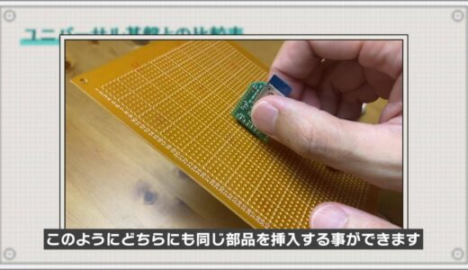
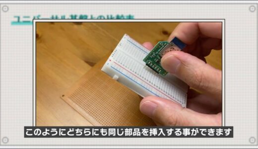
The distance between holes, called pin pitch, is the same for both.
Therefore, the same component can be inserted in either side as shown in the figure below.
The amount of current that can flow depends on the thickness of the wire and the thickness of the solder.
However, be careful not to pour too much because it will scorch the substrate.
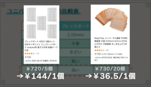
As for price, universal boards tend to be cheaper because of their simpler structure.
For example, if you look at Amazon, you will see that universal boards are cheaper, as shown in the figure below.
How to use a breadboard
Next, we will explain the basic usage of breadboards.
A breadboard has many holes, but broadly speaking, they are divided into two categories by function: one for power GND and the other for signals.
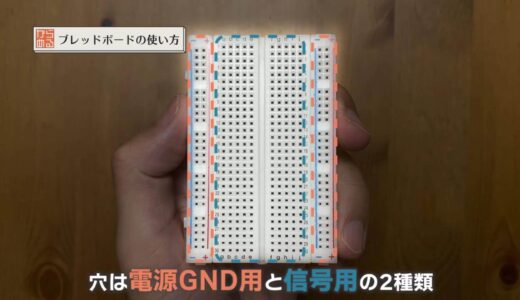
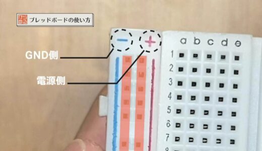
The holes for power GND are the “red and blue wires in a vertical line” shown in the figure below, each connected internally in a vertical line.
It is customary to connect to the power supply side because red is positive, and to the GND side because blue is negative.
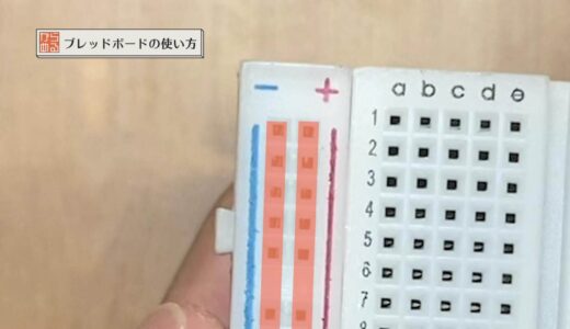
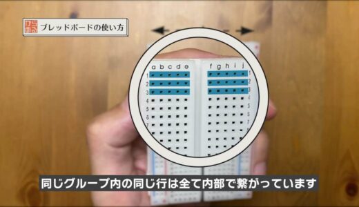
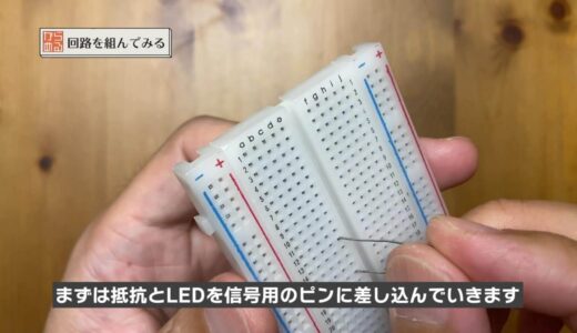
The signal use is the area within the blue dotted line indicated by the finger. As in Excel, the area corresponding to columns is assigned alphabetical characters and the area corresponding to rows is assigned numerical characters.
As shown in the figure below,columns ” a-e” on the left and“f-j”on the rightare in different groups because they are separated internally.
However, the rows “a-e” and “f-j” are in the same group, so the same rows are all connected internally.
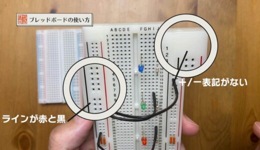
Depending on the item, red and black may be used or there may be no plus and minus as shown in the figure below, but the usage is exactly the same.
Breadboard Structure
To understand this a little better, let’s check out the internals of a breadboard.
I will disassemble the board I had left over on hand.
First, peel off the double-sided tape and you will see many metal bars as shown in the following figure.
These metal bars are all connected to each other. First, let’s remove the bar for the signal.

Then the terminals as shown in the figure below appeared.
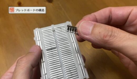
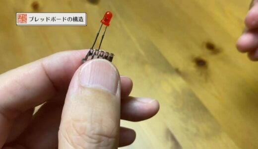
When viewed up close, these terminals are shaped to pinch the legs of the component as shown in the figure below.

When the parts are actually inserted, they will look like the figure below.
Now we will also remove the metal bar corresponding to the power supply GND.
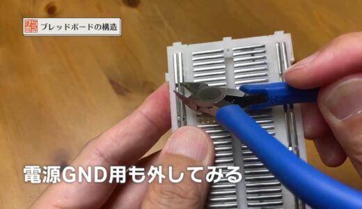
This one is exactly the same in shape, just longer in length.
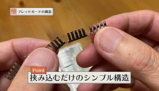
As you can see, we hope you understand that “breadboard is a simple structure with component legs sandwiched together on the back side.
LED lighting circuit creation
Now that you have a better understanding, let’s actually build a circuit.
Here, we will make the standard LED lighting circuit shown in the following figure.
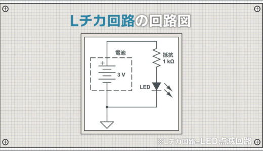
First, resistors and LEDs are plugged into the pins for signals.
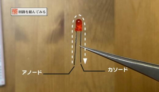
Note that LEDs are oriented.
The longer leg is the anode and the shorter leg is the cathode, Current can only flow from the anode to the cathode.
Since one side of the resistor and the anode side of the LED are connected in the circuit The resistor and LED anodes are connected in the circuit, so they should be in the same row as shown in the figure below.

Next, connect the battery.
You can plug in the pins for signals, but this time we want to learn how to use the power GND, so we will connect it once to this vertical line.
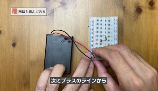
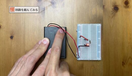
Next, connect the positive line to the leg of the resistor to which the LED is not connected, and connect the negative line to the cathode side of the LED.
The circuit is now complete and the LEDs are successfully attached.
This is the basic usage of the breadboard.
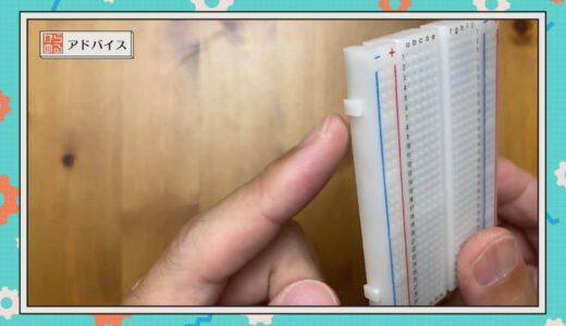
advice of a point (advice that may be helpful to some people)
Most breadboards are uneven, as shown in the figure below, and can be made larger and larger by connecting them like Lego blocks. Please try this when you run out of size.
summary
In this issue, we have explained how to use breadboards for those who are just starting out in electronics.
It is not difficult to use, and you will quickly get used to it once you actually put it together.
\電子工作歴9年の私のイチ押し!ELEGOOの電子工作キット/