Hello, this is Bono.
We often need to know the circuit diagram of a microcontroller board, so we have compiled a circuit diagram of a microcontroller board that is often used.
It would be useful to bookmark this page or otherwise keep it readily available.
Click here for a pin distribution summary.
Arduino Series
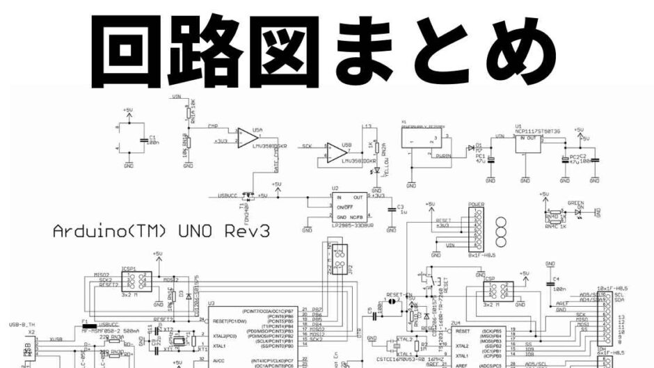
Arduino Uno
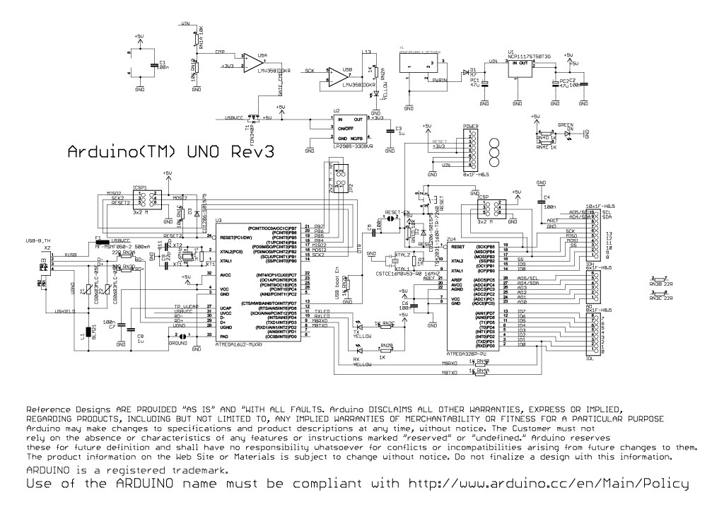
https://www.arduino.cc/en/uploads/Main/Arduino_Uno_Rev3-schematic.pdf
Arudino Mega2560
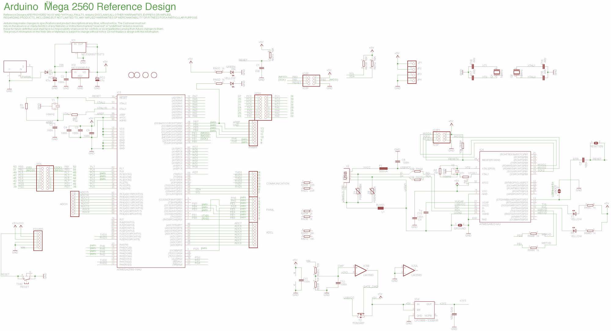
https://www.arduino.cc/en/uploads/Main/arduino-mega2560-schematic.pdf
Arduino DUE
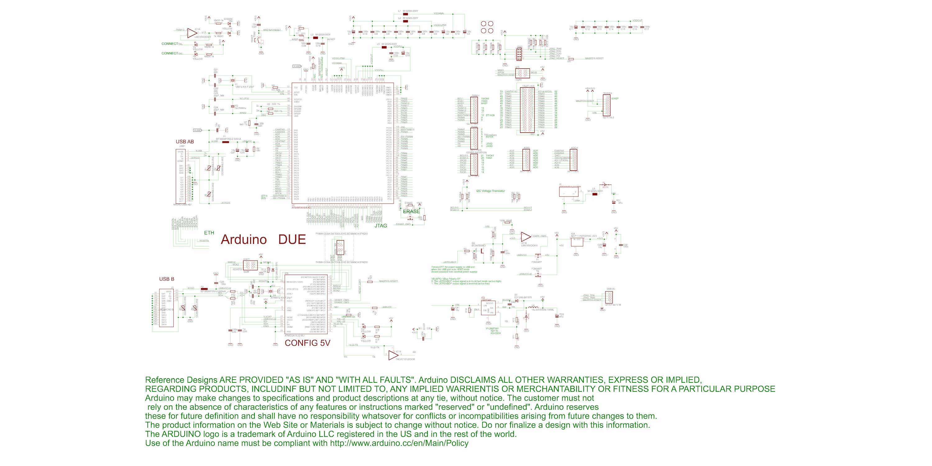
https://www.arduino.cc/en/uploads/Main/arduino-Due-schematic.pdf
Arduino Nano
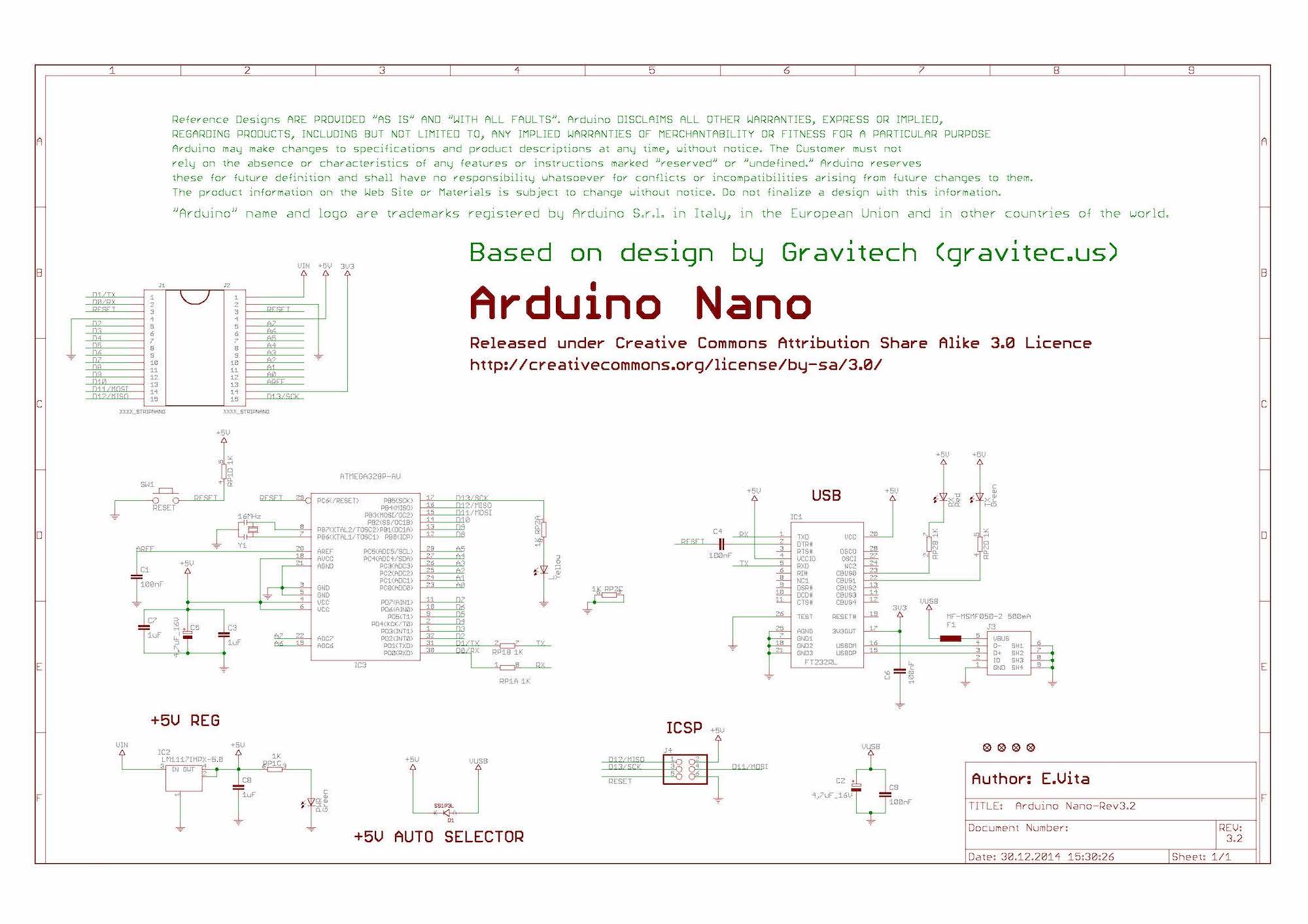
https://www.arduino.cc/en/uploads/Main/Arduino_Nano-Rev3.2-SCH.pdf
RaspberryPi Series
Basically, it is summarized here -> https://www.raspberrypi.com/documentation/computers/raspberry-pi.html
Caution! The following circuit diagram is a simplified version that only describes the circuit around connectors and power supply. Please note that “not all components are listed.
Raspberry Pi Model B+
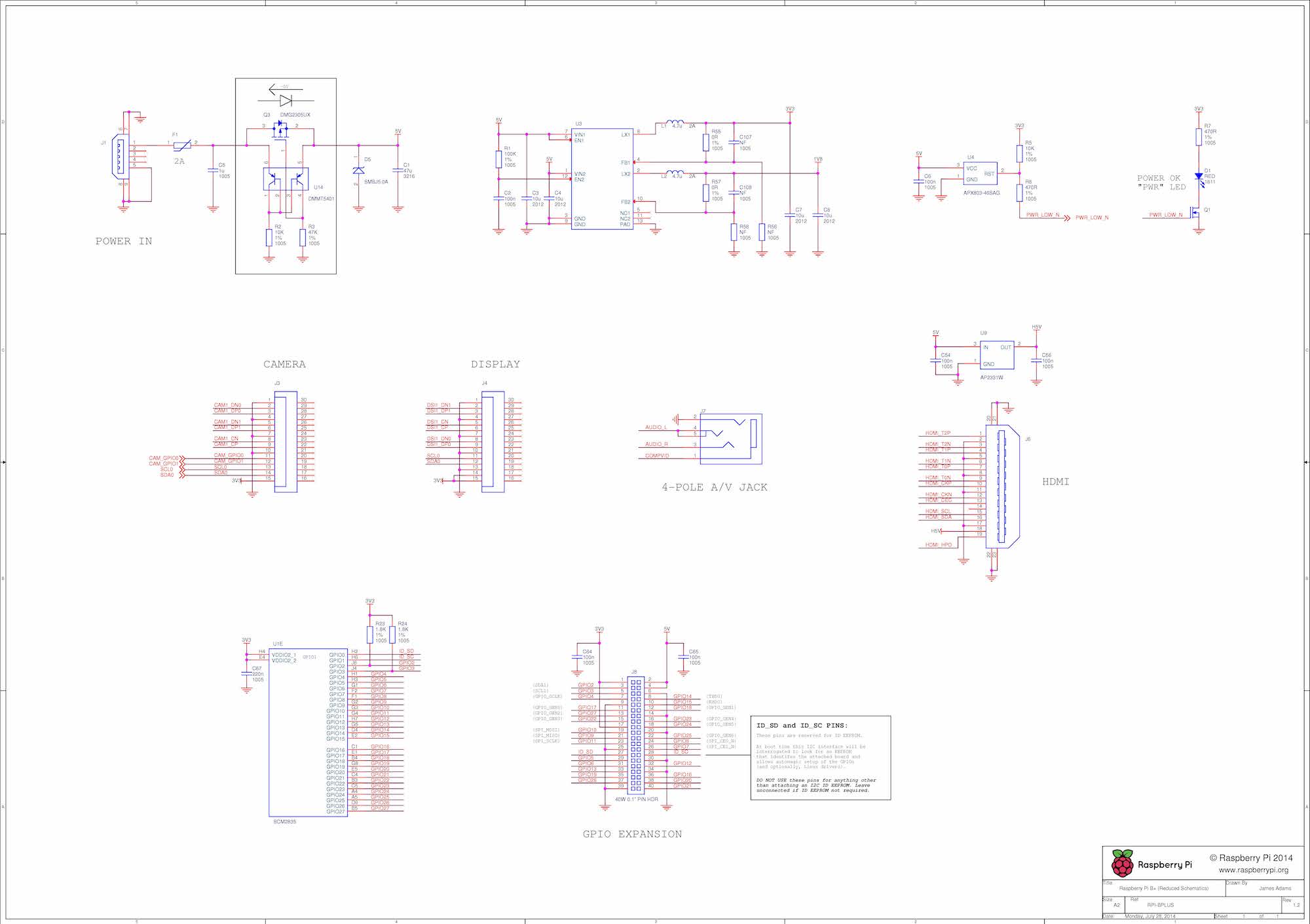
https://datasheets.raspberrypi.com/rpi/raspberry-pi-b-plus-reduced-schematics.pdf
Rapsberry Pi 2 Model B
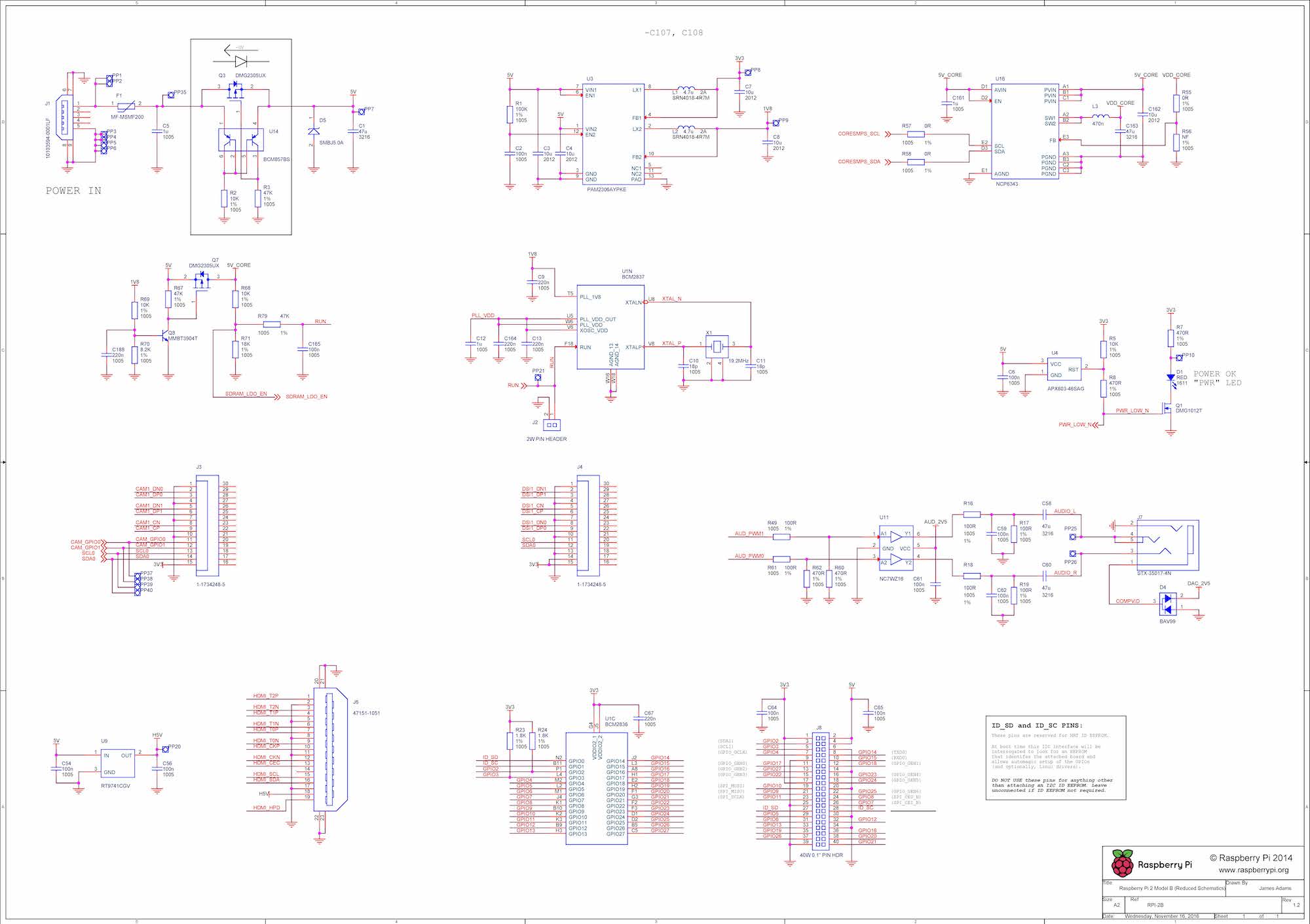
https://datasheets.raspberrypi.com/rpi2/raspberry-pi-2-b-reduced-schematics.pdf
Rapsberry Pi 3 Model B
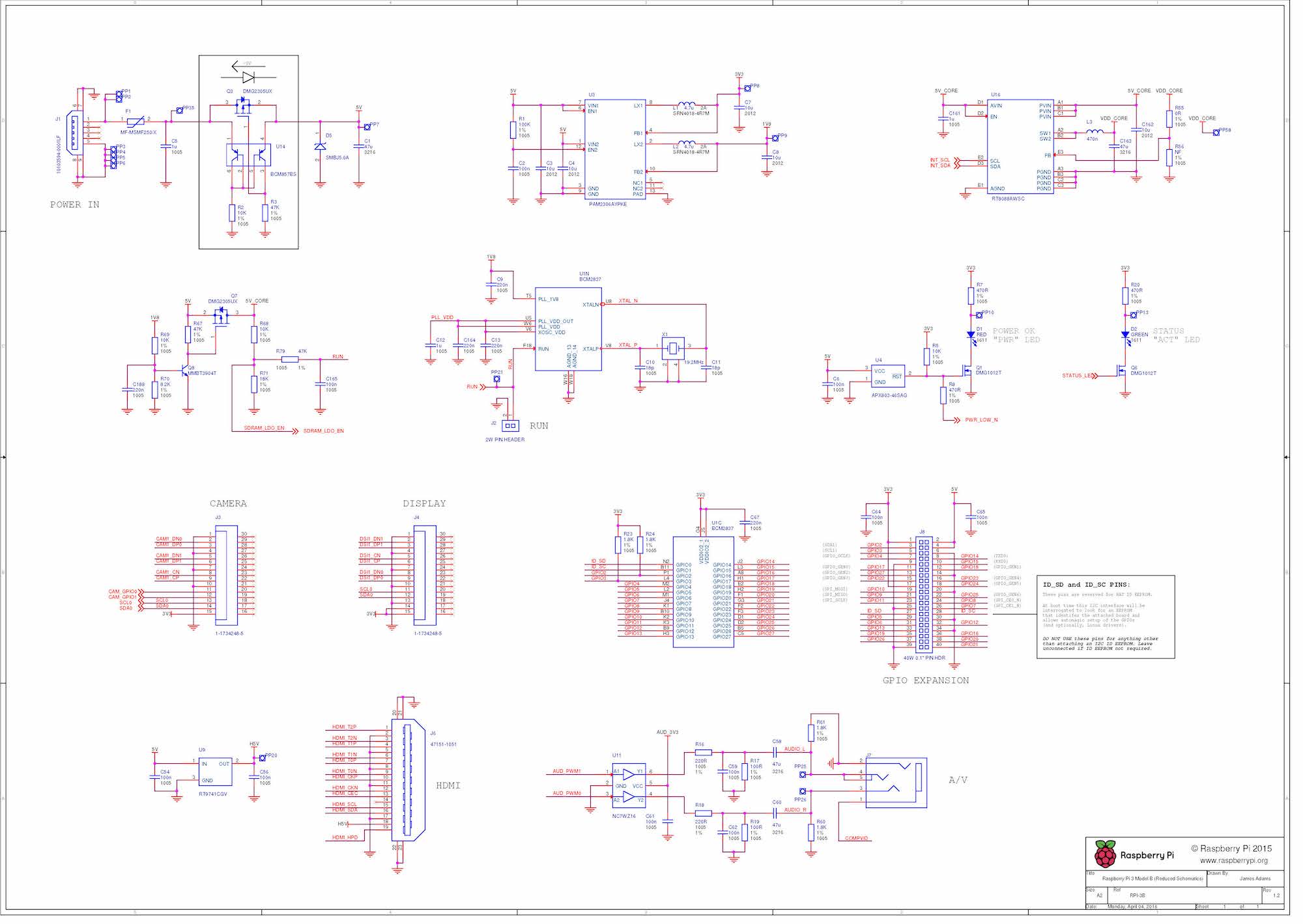
https://datasheets.raspberrypi.com/rpi3/raspberry-pi-3-b-reduced-schematics.pdf
Rapsberry Pi 4 Model B
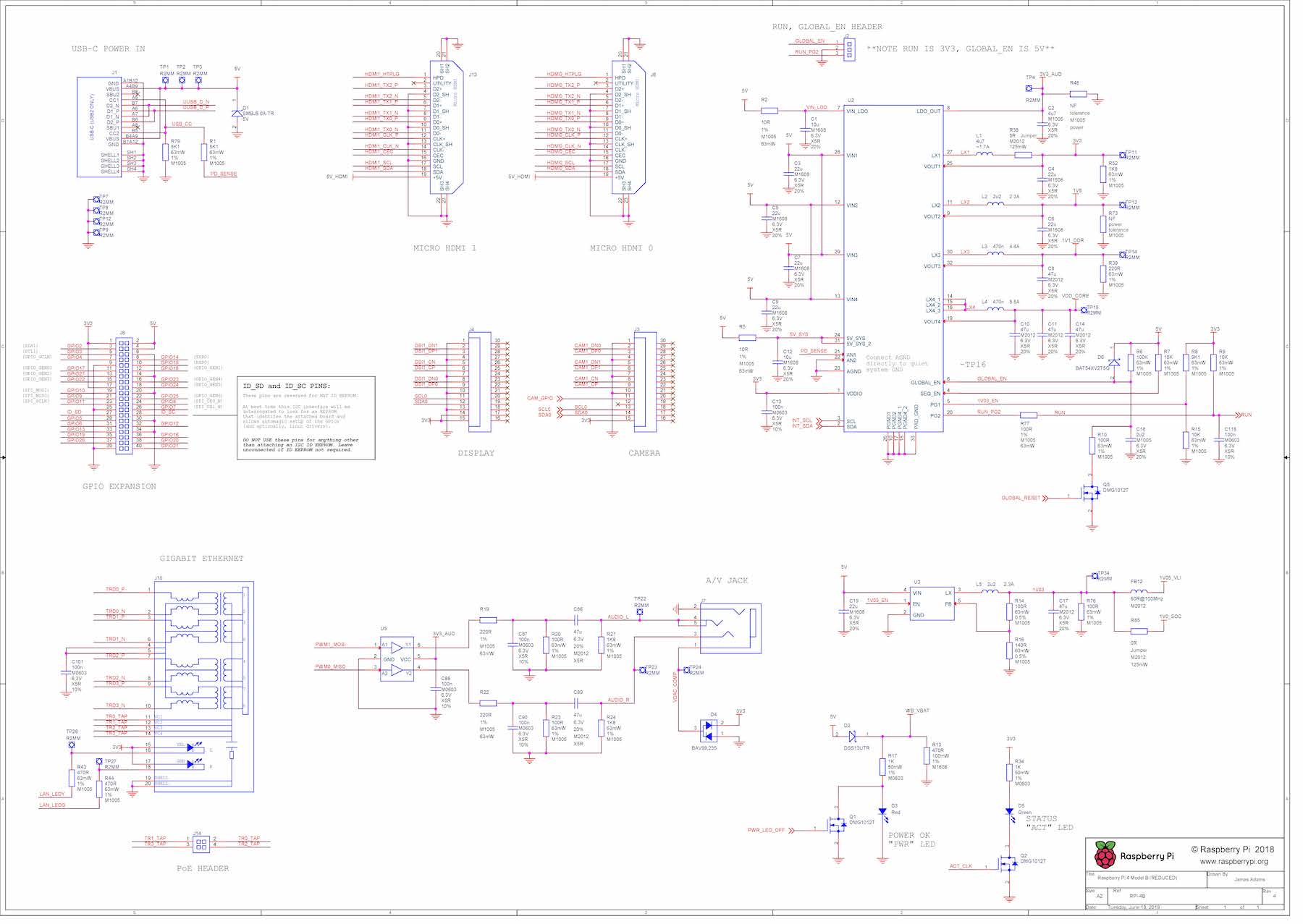
https://datasheets.raspberrypi.com/rpi4/raspberry-pi-4-reduced-schematics.pdf
Raspberry Pi Zero W
I couldn’t find Zero WH, so I had no choice but to post Zero W.
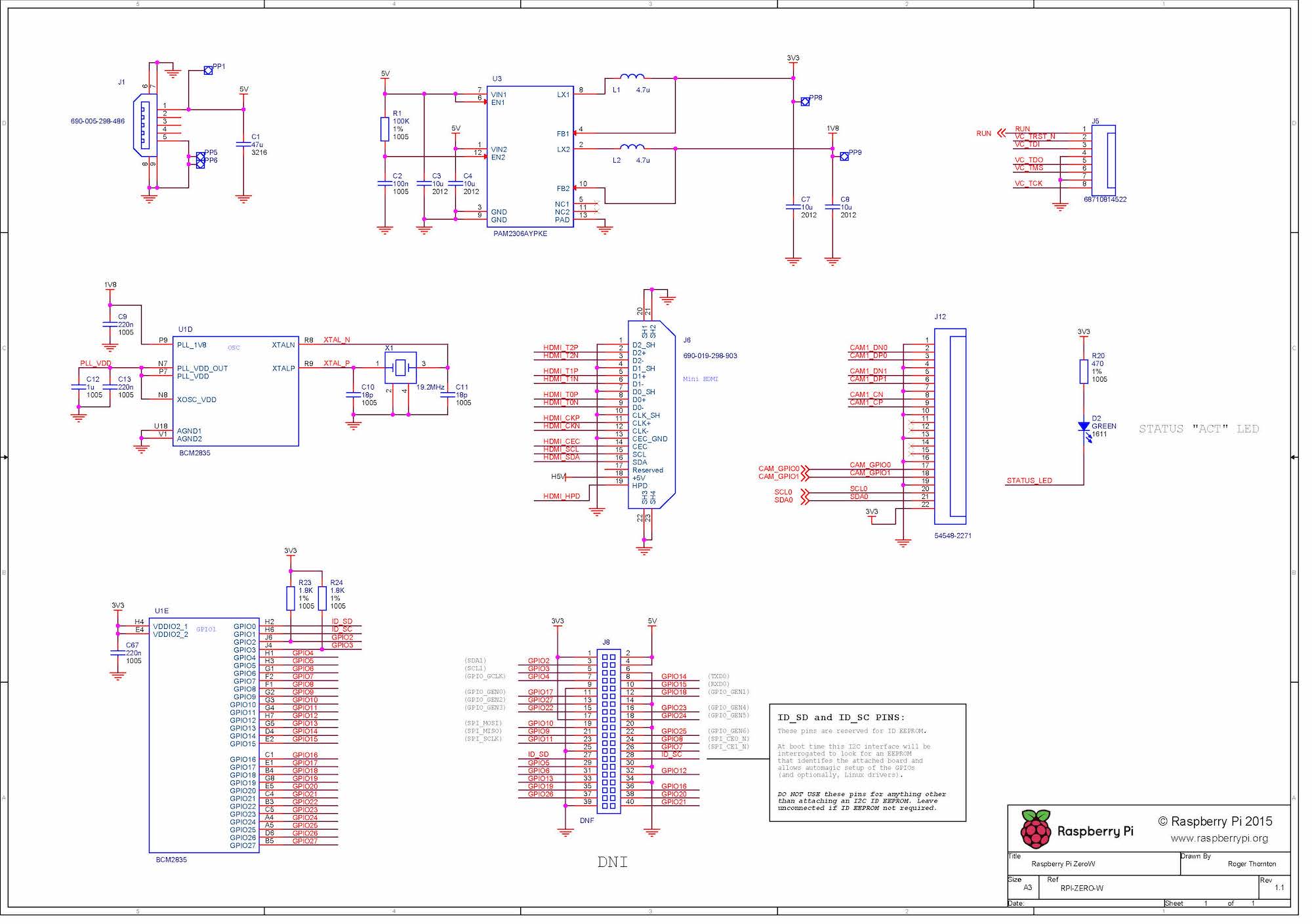
https://datasheets.raspberrypi.com/rpizero/raspberry-pi-zero-w-reduced-schematics.pdf
Raspberry Pi Pico
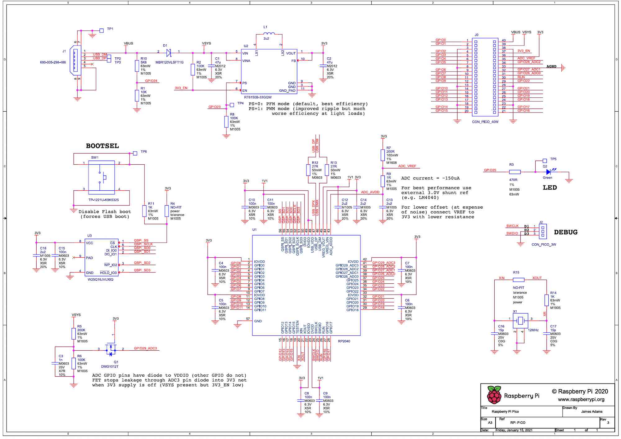
https://datasheets.raspberrypi.com/pico/pico-datasheet.pdf
Raspberry Pi (complete schematic)
I have received information from a follower that the full schematic, not the simplified version, is available here (thank you, Mopurun).
It doesn’t specify which type of Raspberry Pi it is, but since it doesn’t say 2 or 3 and it is dated April 2012, it is natural to assume that it is probably the first generation schematic.
Personally, one thing that puzzles me is the difference that in the schematic here, the 5V to 3.3V is made with a linear regulator called NCP1117, while in the excerpted version described above, it is made with a switching method.
I think the complete version is the correct schematic because the board at hand had NCP1117 mounted on it, but I wonder if there is also a switching system…?
If anyone knows, please let me know.
M5Stack
BASIC
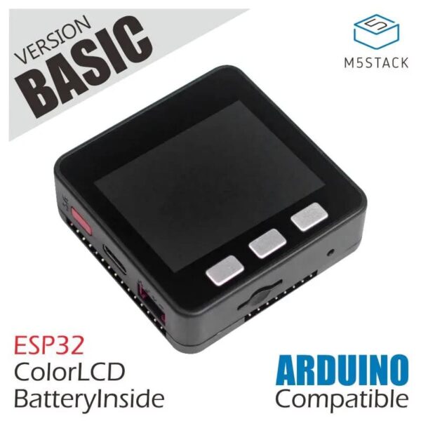
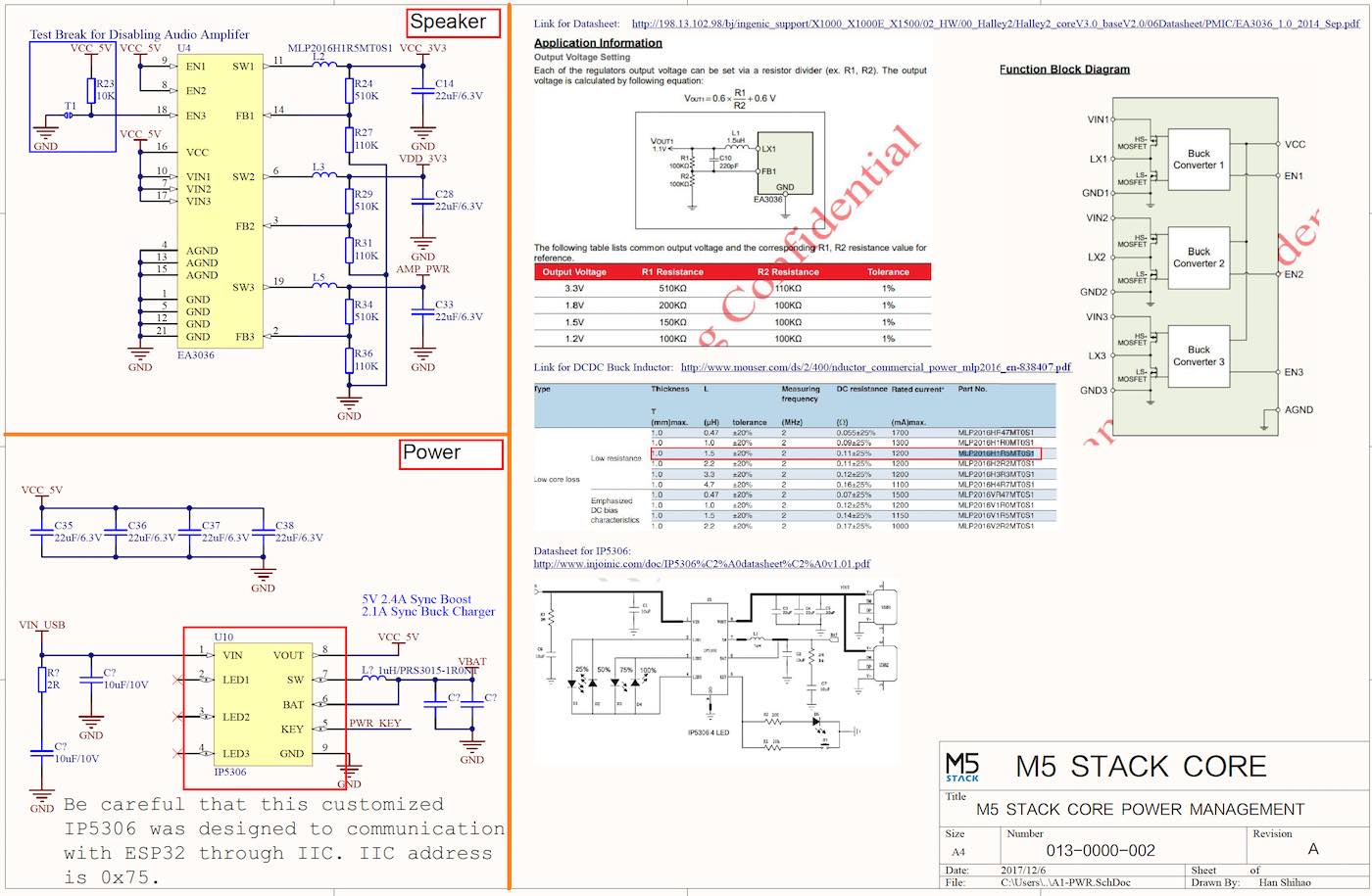
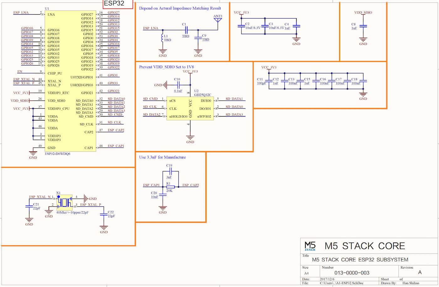
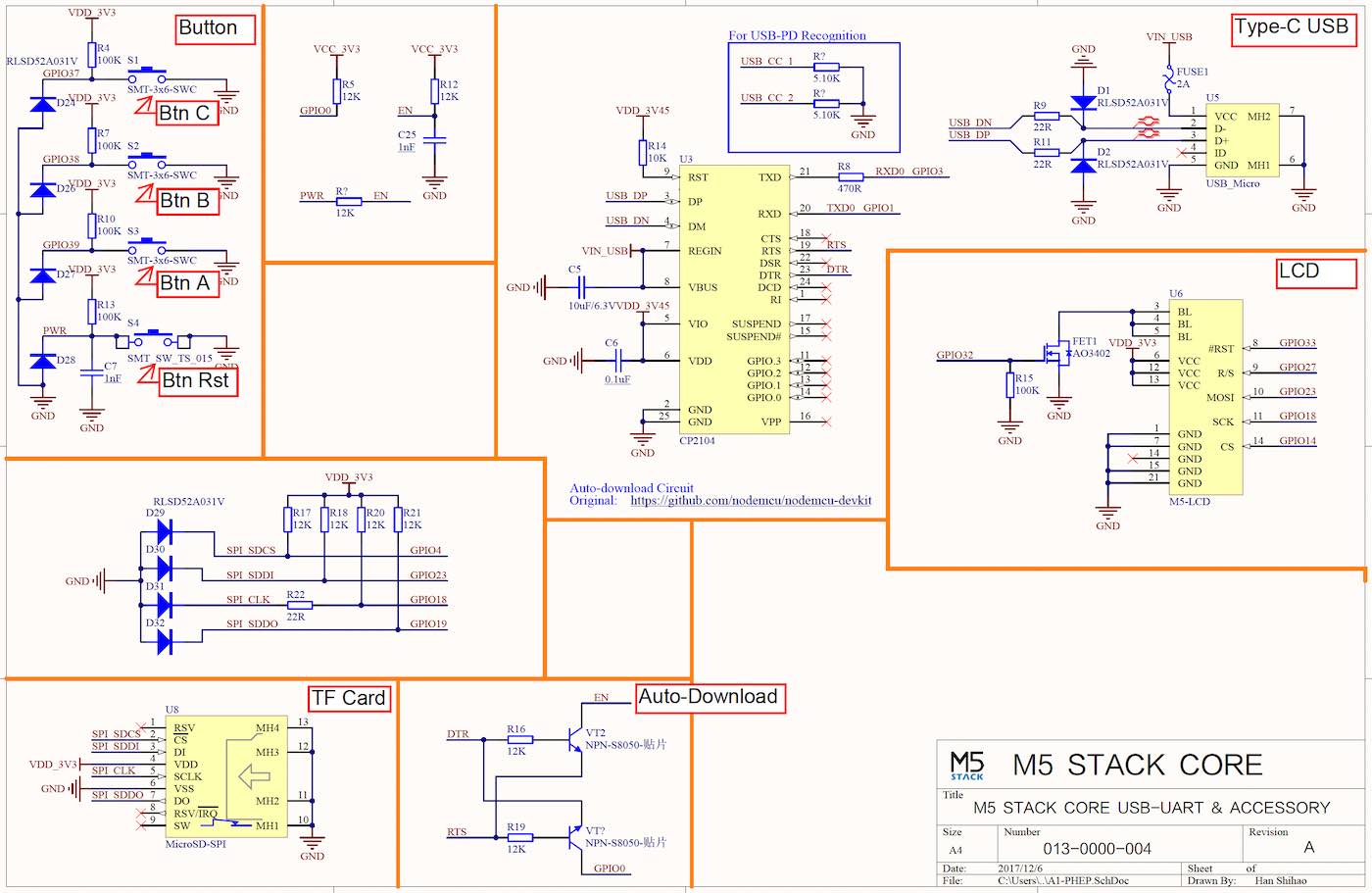
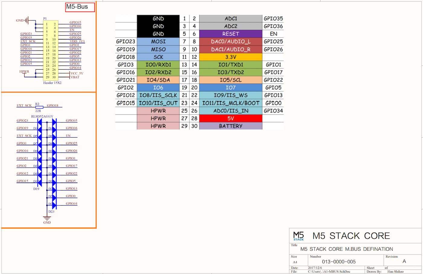
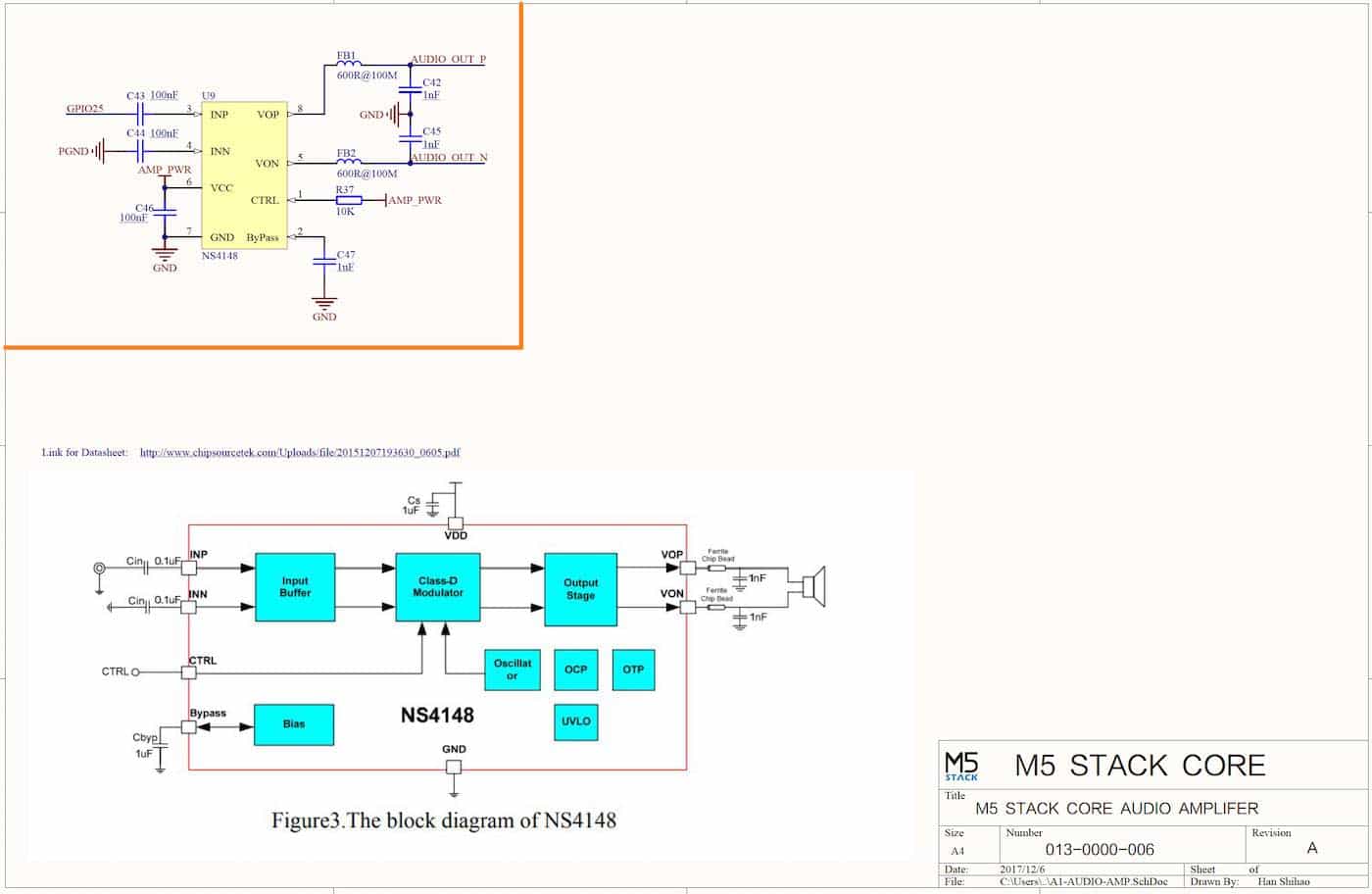
https://github.com/m5stack/M5-Schematic/blob/master/Core/Basic/M5-Core-Schematic(20171206).pdf
CORE2
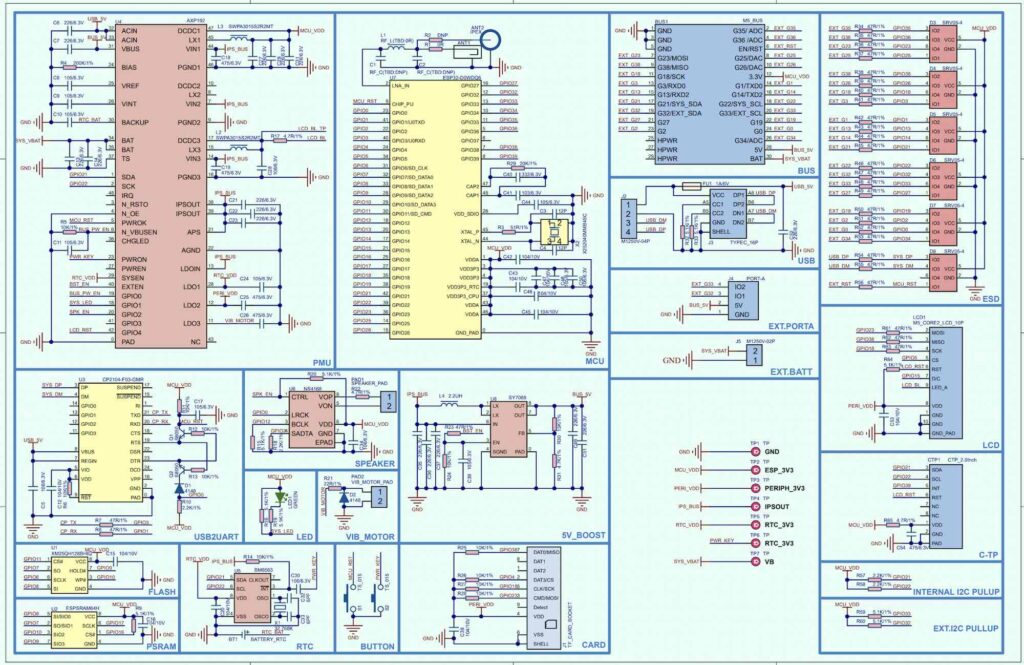
https://m5stack.oss-cn-shenzhen.aliyuncs.com/resource/docs/schematic/Core/CORE2_V1.0_SCH.pdf
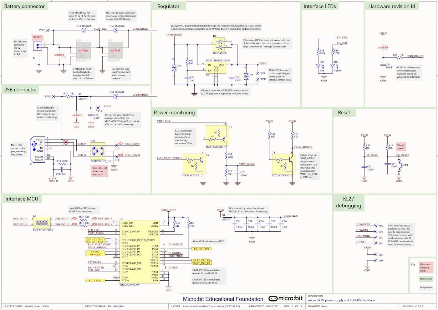
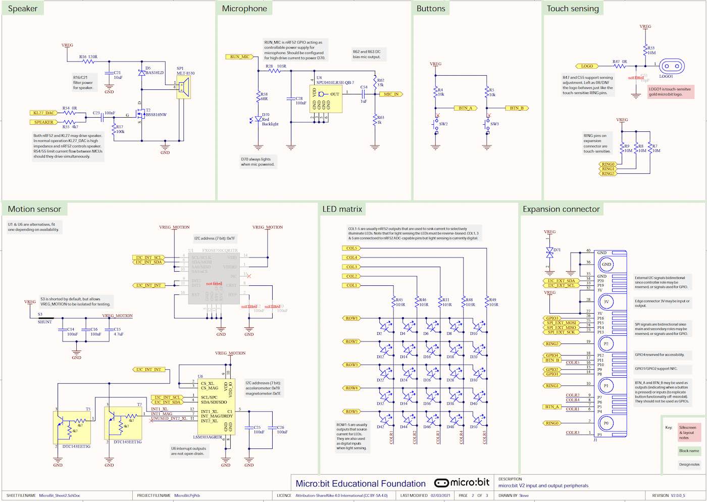
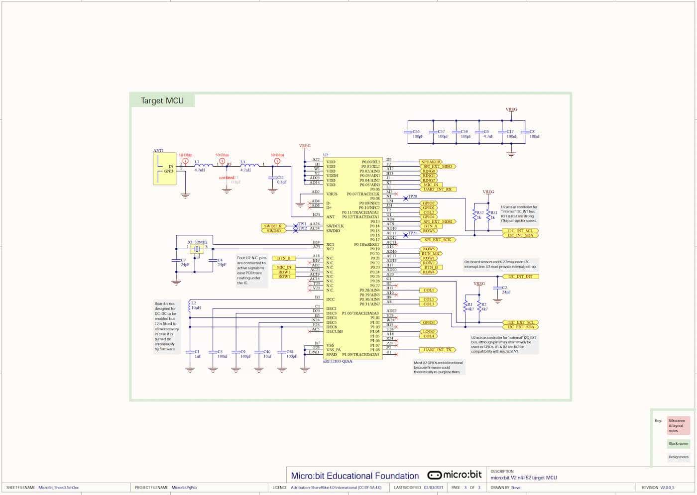
Microbit
obniz
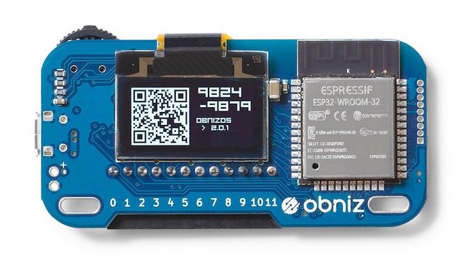
I can’t find it, and, it’s private?
 Start electronics